
Biological particle hot-blast stove

A technology of biological particles and hot blast stoves, applied in fluid heaters, lighting and heating equipment, etc., can solve the problems of pipeline tempering, fuel type restrictions, size requirements, etc., to reduce heat waste and facilitate cleaning and maintenance , easy replacement effect

Inactive Publication Date: 2015-10-21
HENAN JUFENG BIO ENERGY DEV
View PDF5 Cites 8 Cited by
  • Summary
  • Abstract
  • Description
  • Claims
  • Application Information

AI Technical Summary

Problems solved by technology

[0002] In the field of industrial technology, biomass hot blast stoves are already a relatively common equipment, especially in the normal use of various boilers, hot blast stoves have great industrial uses, such as drying, thermal spraying, breeding, etc. Most of the hot blast stoves currently in use use biomass energy such as straw as the main fuel. However, during the use of this type of furnace, most of the biomass particles burned are insufficient and the biomass energy is not fully utilized. Technical problems, incomplete combustion of biomass particles is also easy to form harmful particulate matter such as PM2.5, which brings great pollution to the environment; due to the unreasonable arrangement of the flue gas return and the external cold air return, the exchange of heat is not sufficient and the heat is extremely high Land loss and waste; Most of the feed materials are fed to the combustion chamber by the feed fan, which is easy to cause tempering in the pipeline; after the flue gas is exchanged with the cold air, it is directly discharged into the atmosphere without recycling, resulting in waste of heat; The feed pipe of the biomass pellet hot blast stove has requirements on the size of the fuel particles, which limits the type of fuel used

Method used


Image

  • Biological particle hot-blast stove
  • Biological particle hot-blast stove

Examples


Embodiment Construction

[0018] The present invention will be further described in detail below in conjunction with the drawings.

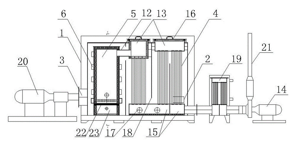
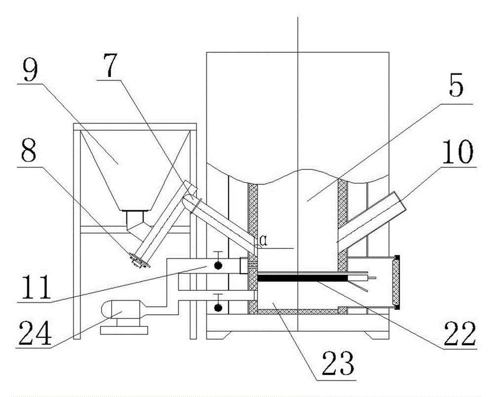
[0019] See figure 1 with figure 2 As shown, a biological particle hot air stove includes a furnace body 1. Both sides of the furnace body 1 are provided with a cold air inlet 2 and a hot air outlet 3 respectively. The hot air outlet 3 is connected to a circulating fan 20, and the cold air inlet 2 is provided with an air filter device. The air to be heat exchanged is drawn in for dust removal and filtration to reduce the dust carried by the air from adhering to the wall of the heat exchange pipe 4, which affects the heat exchange effect; the furnace body 1 is provided with a furnace 5, and the outer periphery of the furnace 5 is provided with a number of heat exchange fins The fins 6 and the heat exchange fins 6 increase the heat exchange area; the furnace 5 is provided with a feeding tube 7 obliquely on one side, and the angle α between the center line of the feeding tube 7...


PUM


Abstract

The invention relates to a hot-blast stove, in particular to a biological particle hot-blast stove. The biological particle hot-blast stove comprises a stove body, wherein a cold air inlet and a hot air outlet are respectively formed at the two sides of the stove body; the hot air outlet is connected with a circulating fan; a hearth is arranged in the stove body, and is connected with a blower through a blowing pipe; a moving grate is mounted at the lower part of the hearth; the upper part of the hearth is communicated with an upper smoke tank through a smoke pipe; the upper smoke tank and a lower smoke tank are communicated through multiple heat exchange pipes; multiple separation plates are arranged among the heat exchange pipes; the lower smoke tank is communicated with one side of an afterheat heat exchanger; the other side of the afterheat heat exchanger is connected with an induced draft fan and a chimney in sequence; a feed pipe is aslant arranged at one side of the hearth, and is connected with a feed mechanism; and a fire observing port is aslant formed in the hearth at the opposite side of the feed pipe. The invention provides the biological particle hot-blast stove; and the device fully combusts fuels, reduces the environmental pollution, improves the combustion efficiency of the fuels, and adds the afterheat heat exchanger to reduce the heat waste.

Description

Technical field [0001] The invention relates to a hot blast stove, in particular to a biological particle hot blast stove. Background technique [0002] In the field of industrial technology, biomass hot blast stove is already a relatively common equipment, especially in the normal use of various boilers, hot blast stoves have great industrial uses, such as drying, thermal spraying, breeding, etc. Most of the hot blast stoves currently in use use biomass energy such as straw as the main fuel. However, in the use of this type of burner, most of them have insufficient combustion of biomass particles and insufficient use of biomass energy. Technical problems. Insufficiently burned biomass particles can also easily form harmful particles such as PM2.5, which will cause great pollution to the environment; due to the unreasonable arrangement of the flue gas return path and the outside cold air return path, the heat exchange is not sufficient and the heat is extremely high. Earth loss ...

Claims


Application Information

Patent Timeline
Patent Type & Authority Applications(China)
IPC IPC(8): F24H6/00F24H9/00F24H9/18
Inventor 高海华管永伟赵胜刚李婧张平刘善民候明旗
Owner HENAN JUFENG BIO ENERGY DEV
Learn More