Circuit compensation network of non-contact power supply ultrasonic vibration system based on efficiency

A technology of non-contact power supply and ultrasonic vibration, applied in the direction of electromagnetic wave system, etc., can solve the problems of consuming large reactive power, reducing system power factor and transmission efficiency, limiting power transmission capacity, etc.

Active Publication Date: 2015-10-21
TIANJIN UNIV
View PDF6 Cites 4 Cited by
  • Summary
  • Abstract
  • Description
  • Claims
  • Application Information

AI Technical Summary

Problems solved by technology

Leakage flux prevents the energy emitted by the primary coil from being completely absorbed by the secondary coil, and some of it is stored inside the coupler, which not only limits its power transmission capability, but also increases its own loss
The load of the rotating electromagnetic coupler is the ultrasonic vibration system (transducer, horn and tool). The

Method used


Image

  • Circuit compensation network of non-contact power supply ultrasonic vibration system based on efficiency
  • Circuit compensation network of non-contact power supply ultrasonic vibration system based on efficiency
  • Circuit compensation network of non-contact power supply ultrasonic vibration system based on efficiency

Examples


Embodiment

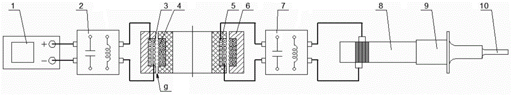
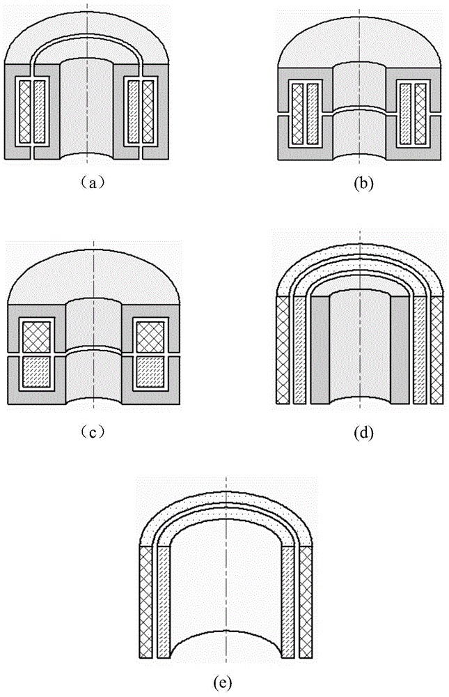
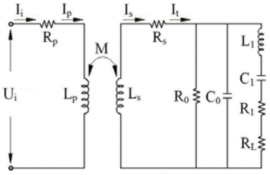
[0097] Below to Figure 7 The U-shaped concentric magnetic core cylindrical induction electromagnetic coupler shown is taken as an example to illustrate the specific method of compensation components and coil optimization. The non-contact electromagnetic coupler is made of manganese-zinc ferrite PC40 material. The size parameters are shown in Table 1. The transducer used The electrical parameters of the device are listed in Table 2. The relationship between the self-inductance of the coupler coil and the AC resistance and the number of turns of the coil measured in the experiment is shown in Figure 8-10 , the coupling coefficient k between the coils is shown in Table 3.

[0098] Table 1 Dimensional parameters of U-type concentric magnetic core cylindrical induction electromagnetic coupler (mm)

[0099] d1

d2

d3

d4

H

a

b

g

65

82

84

101

25

18

4

1

[0100] Table 2 Electrical parameters of ultrasoni...


PUM

PropertyMeasurementUnit
Radiusaaaaaaaaaa

Abstract

The invention discloses a circuit compensation network of a non-contact power supply ultrasonic vibration system for realizing maximum transmission efficiency. The circuit compensation network comprises a primary compensation network and a secondary compensation network. The primary compensation network is connected between an ultrasonic power supply and a primary coil of a non-contact electromagnetic coupler to compensate reactive power of the system and make voltage and current output by the power supply in phase. The secondary compensation network is connected between a secondary coil of the non-contact electromagnetic coupler and an ultrasonic vibrator to realize highest-efficiency energy transmission by optimizing the parameters of a secondary compensation element(s), wherein the compensation element(s) is/are an inductor or/and a capacitor. The circuit compensation network of the invention can be applied to rotary ultrasonic machining, ultrasonic welding, and other occasions in which a non-contact electromagnetic coupler needs to be adopted to supply power to an ultrasonic vibrator. Highest-efficiency energy transmission is realized by optimizing the parameters of the secondary compensation element(s).

Description

technical field [0001] The invention relates to a technology of using a non-contact rotating electromagnetic coupler to supply power to an ultrasonic transducer, in particular to a circuit compensation method for realizing the maximum transmission efficiency of the non-contact energy transmission system. Background technique [0002] Rotary ultrasonic machining uses consolidated diamond tools (electroplated or sintered diamond tools) for ultrasonic vibration and high-speed rotation at the same time. Widely used in the processing of hard and brittle materials such as engineering ceramics, composite materials, titanium alloys, etc., rotary ultrasonic machining can effectively improve material removal rate, improve workpiece surface quality and prolong tool life. Traditional rotary ultrasonic machine tools mostly use the power supply method of brush slip ring. This contact power supply method is prone to sparks and wear, and cannot be used in inflammable and explosive harsh en...

Claims


Application Information

Patent Timeline
IPC IPC(8): H02J17/00
Inventor 林彬朱学明刘礼平
Owner TIANJIN UNIV
Why Eureka
Try Eureka