Related to continuous fiber reinforced thermoplastic pipe and production method

A technology of reinforcing thermoplastic and continuous fibers, applied in rigid pipes, hoses, pipes, etc., can solve the problems of efficient production hindering the application of RTP pipes, difficulty in infiltrating fibers in-line dipping, and inability to resist the use of high-pressure products. Small footprint and reduced equipment investment

Active Publication Date: 2017-10-20
深圳鑫宝通材料科技有限公司
View PDF2 Cites 2 Cited by
  • Summary
  • Abstract
  • Description
  • Claims
  • Application Information

AI Technical Summary

Problems solved by technology

As described in the patent document CN103878990A, the products produced by this method have high compressive capacity and good safety, but the production line of this process is very long, generally about 80M long, and even more than 100M for multi-layer reinforced thick tubes. The technology of heating and melting between layers is relatively high, the control is not good, and quality problems are prone to occur. At present, the mature European production line needs about 20-30 million RMB. The domestic production line is still in the research and development stage, and it is expected to need 10 million RMB. Above, this kind of high cost input and low efficiency production hinder the application of RTP pipe
Although the method described in the patent document CN102363363A is simple, the current online fiber dipping technology is far from meeting the requirements. The online fiber dipping is difficult to soak, and the product produced has too many microbubbles and cannot be used as a high-pressure resistant product.

Method used


Image

  • Related to continuous fiber reinforced thermoplastic pipe and production method
  • Related to continuous fiber reinforced thermoplastic pipe and production method

Examples


Embodiment Construction

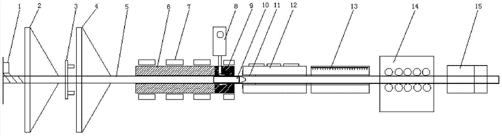
[0027] The present invention will be further described below in conjunction with accompanying drawing, and the structure and principle of this device are very clear to those skilled in the art. It should be understood that the specific embodiments described here are only used to explain the present invention, not to limit the present invention.

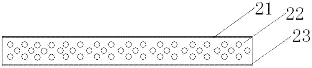
[0028] Such as figure 2 As shown, the pipeline in the present invention is composed of an inner layer and a braided reinforcing layer structure on the inner layer, an outer layer is arranged on the reinforced layer structure, and the three-layer structure is formed at one time, wherein the inner layer is made of a thermoplastic film or sheet to be wound or Portrait mode composition. The reinforcement layer weaves, wraps, and longitudinally arranges the fibers pre-impregnated with thermoplastic materials on the inner layer according to the design requirements. When the thermoplastic material of the inner tube and the reinforcing lay...


PUM

PropertyMeasurementUnit
thicknessaaaaaaaaaa
thicknessaaaaaaaaaa

Abstract

The invention relates to the technical field of glass fiber and pipeline forming, particularly to a thermoplastic pipeline related to continuous fiber reinforcement and a producing method. The pipeline comprises an inner layer, a weaving enhancement structure layer on the inner layer and an outer thermoplastic protective layer on the inner layer and the enhancement structure layer, wherein the three-layer structure is integrally formed; the inner layer adopts thermoplastic membranes or sheets; the enhancement layer is prepared through weaving, twining and longitudinally configurating preimpregnated thermoplastic fiber yarns; the outer layer is extruded with an extruder on the inner layer and the enhancement layer through the adoption of a thermoplastic material, so that the three-layer structure is integrated into a whole body, wherein the pipeline specification is below D1000 mm; the working pressure is 1-15 MPa. According to the thermoplastic pipeline and the producing method, the conventional RTP pipe three-layer structure is reserved, and the conventional multistep shaping method is changed to one-step shaping, so that the production line length is shortened by a half, and the equipment input is greatly decreased; the novel product is more stable in quality, higher in internal pressure strength and applicable to continuous production.

Description

[technical field] [0001] The invention relates to the technical field of glass fiber and pipe molding, in particular to a continuous fiber reinforced thermoplastic pipe and a production method. [Background technique] [0002] In the past ten years, continuous fiber reinforced thermoplastic pipes (Reinforced Thermoplastic Pipes) has been a hot research direction in the field of international pipes, because it has very obvious advantages, which can not only exert the high strength of fibers, withstand high pressure, but also maintain the good properties of thermoplastics. Flexibility and corrosion resistance have a broad market in the application of high-pressure pipes such as oil pipelines, gas pipes, water supply and drainage pipes. [0003] The traditional RTP pipe has a three-layer structure, that is, the inner and outer extruded thermoplastic pipes, and the middle layer is a fiber-reinforced layer or a steel wire-reinforced layer. The method used is to extrude a thermopl...

Claims


Application Information

Patent Timeline
Patent Type & Authority Patents(China)
IPC IPC(8): B29D23/00F16L9/12F16L11/08
CPCB29D23/00F16L9/121F16L11/083
Inventor 王云凯游雄伟麻加伟谢锋
Owner 深圳鑫宝通材料科技有限公司
Why Eureka
Try Eureka