
Vibration fault diagnosis method of hydroelectric generating set

A technology for fault diagnosis and hydroelectric units, which is applied in vibration testing, machine/structural component testing, electrical digital data processing, etc. It can solve problems such as inability to guarantee diagnostic accuracy, poor maintainability of knowledge base, and long diagnostic system establishment cycle.

Inactive Publication Date: 2015-10-28
XIAN UNIV OF TECH
View PDF3 Cites 29 Cited by
  • Summary
  • Abstract
  • Description
  • Claims
  • Application Information

AI Technical Summary

Problems solved by technology

The causal analysis diagnosis method is an offline post-diagnosis work, which cannot realize real-time online diagnosis; the fault tree diagnosis method is greatly affected by subjective factors, and cannot diagnose unpredictable faults at the same time; the fuzzy diagnosis method uses a single information, and its diagnosis The accuracy cannot be guaranteed; the expert diagnosis system mainly has problems such as weak reasoning ability, long establishment period of the diagnosis system, and poor maintenance of the knowledge base; the neural network needs a large number of samples to ensure the reliability of its diagnosis; the rough set is subject to subjective constraints when constructing information decision tables. Greater impact
[0006] From the above analysis, it can be seen that the existing vibration fault diagnosis methods have their own limitations. Due to the frequent occurrence of hydroelectric unit accidents, there is an urgent need for an effective hydroelectric unit vibration fault diagnosis method.

Method used


Image

  • Vibration fault diagnosis method of hydroelectric generating set
  • Vibration fault diagnosis method of hydroelectric generating set
  • Vibration fault diagnosis method of hydroelectric generating set

Examples


Embodiment Construction

[0040]In order to make the purpose, technical solution and advantages of the present invention more clear, the present invention will be further elaborated below in conjunction with the accompanying drawings and embodiments. It should be understood that the specific embodiments described here are only used to explain the present invention, not to limit the present invention.

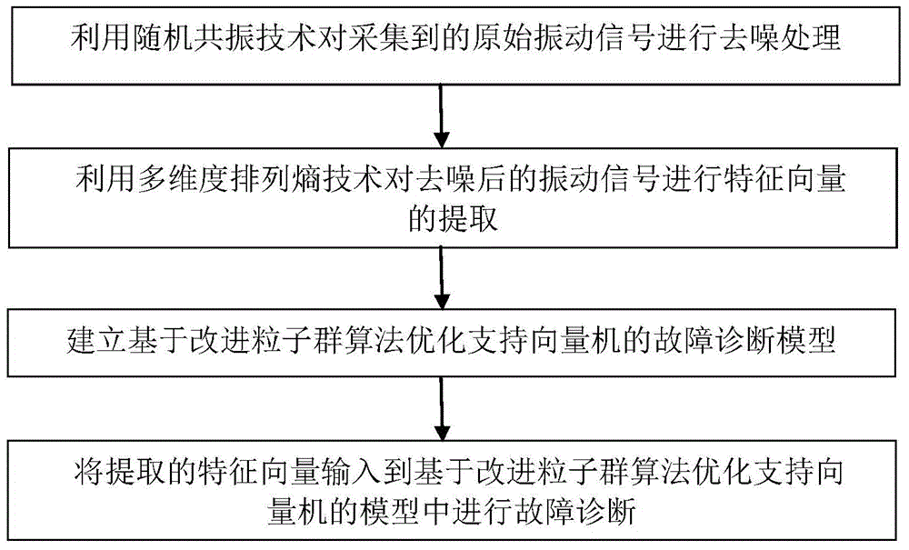
[0041] figure 1 The implementation flow of the method for diagnosing the vibration fault of the hydroelectric unit provided by the embodiment of the present invention is shown.

[0042] The vibration fault diagnosis method of the hydroelectric unit in the embodiment of the present invention is carried out according to the following steps:

[0043] Step 1: Use stochastic resonance technology to denoise the collected original vibration signals: Since the hydroelectric unit is a rotating machine, the vibration signals collected by the sensor often contain a lot of noise and other interference signals. If t...


PUM


Abstract

The invention relates to a vibration fault diagnosis method of a hydroelectric generating set. The method comprises the steps of: firstly, carrying out denoising processing on collected original vibration signals by utilizing a random resonance technology; secondly, carrying out characteristic vector extraction on the vibration signals after the denoising by utilizing a multi-dimensional permutation entropy technology; thirdly, establishing fault diagnosis models of optimized support vector machine based on an improved particle swarm algorithm; fourthly, inputting extracted characteristic vectors into the models of the models of optimized support vector machine based on the improved particle swarm algorithm for fault diagnosis. The method is applicable to the vibration fault diagnosis of the hydroelectric generating set, the diagnosis result is high in precision, the fault type of the generating set can be relatively accurately diagnosed, the reliable diagnosis result is provided to operation maintenance personnel of the generation set, the maintenance personnel can process faults timely and rapidly, and the safety and the economic performance of the operation of the generating set are ensured.

Description

technical field [0001] The invention belongs to the technical field of fault diagnosis, and more specifically relates to a vibration fault diagnosis method of a hydroelectric unit. Background technique [0002] In recent years, the research on vibration fault diagnosis of hydropower units is in full swing. The general steps of fault diagnosis can be divided into three steps: vibration signal processing, feature vector extraction, and fault type diagnosis. [0003] The processing of the vibration signal mainly refers to filtering the original signal, that is, denoising processing. In this respect, domestic and foreign research methods mainly include short-time Fourier transform, wavelet analysis, high-order statistics, chaotic oscillator method and so on. Although the short-time Fourier transform describes the time-varying characteristics of non-stationary signals well to a certain extent, it cannot avoid the defect of fixed time-frequency windows; the wavelet analysis meth...

Claims


Application Information

Patent Timeline
Patent Type & Authority Applications(China)
IPC IPC(8): G01M7/02G06N3/00G06F19/12
Inventor 贾嵘何洋洋党建董开松李臻沈渭程马喜平
Owner XIAN UNIV OF TECH
Learn More