Medium and small power LD parallelly pumped high-power green laser

A medium and small power, laser technology, applied in the field of lasers, can solve the problems of matching coupling characteristics between rods, affecting the stability of the laser system, and instability of the resonator cavity, achieving high thermal stability, reducing high thermal effects, and reducing pump power. Effect

Inactive Publication Date: 2015-10-28
广州安特激光技术有限公司
View PDF5 Cites 4 Cited by
  • Summary
  • Abstract
  • Description
  • Claims
  • Application Information

AI Technical Summary

Problems solved by technology

The main disadvantage of multi-rod series connection is that as the power increases, the thermal lens effect of each laser crystal rod and the frequency doubling crystal will make the resonator unstable. As the pump current increases, the output power will decrease instead. At the same time, this method assu

Method used


Image

  • Medium and small power LD parallelly pumped high-power green laser
  • Medium and small power LD parallelly pumped high-power green laser

Examples


Example Embodiment

[0024] Example one

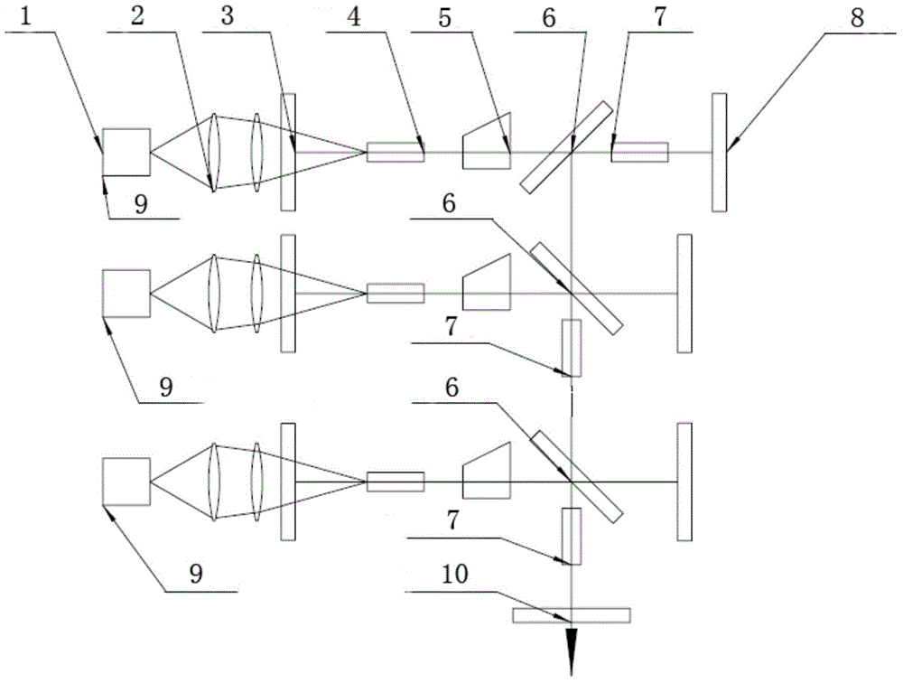
[0025] Please refer to figure 1 The said low- and medium-power LD parallel-pumped high-power green laser includes three frequency-doubled crystals 7, three end-pumped lasers 9 and a resonant cavity. The three end-pumped lasers 9 are arranged in parallel, the optical axes of the three end-pumped lasers 9 are parallel, and two of the three frequency doubling crystals 7 are located in the resonant cavity to form a frequency doubling resonant cavity. One end of the resonant cavity is the second output mirror 10. Each end pump laser 9 includes an end pump device composed of a pump source 1, a coupling mirror 2 and a laser crystal 4, a sub-resonator composed of a first total mirror 3 and a second total mirror 8, and a The Q switch 5 used to modulate the pulsed laser and the first output mirror 6 used to reflect and output the pulsed laser in the resonant cavity form an angle of 45° with the optical axis of the end pump laser 9.

[0026] The first output mirror 6 of...

Example Embodiment

[0031] Example two

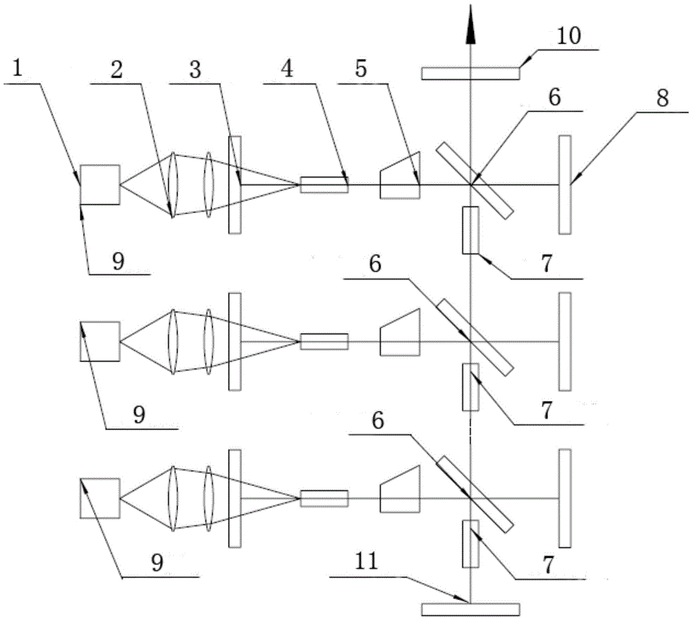
[0032] Please refer to figure 2 The said low- and medium-power LD parallel-pumped high-power green laser includes three frequency-doubled crystals 7, three end-pumped lasers 9 and a resonant cavity. One end of the resonant cavity is the second output mirror 10, and the other end is the third total mirror 11, and the resonant cavity is a straight cavity. Three end-pumped lasers 9 are arranged in parallel, the optical axes of the three end-pumped lasers 9 are parallel, and the three frequency-doubling crystals 7 are all located in the resonant cavity to form a frequency-doubling resonant cavity, the frequency-doubling resonator and each end-pumped laser The optical axis of 9 is vertical. Each end pump laser 9 includes an end pump device composed of a pump source 1, a coupling mirror 2 and a laser crystal 4, a sub-resonator composed of a first total mirror 3 and a second total mirror 8, and a The Q switch 5 used to modulate the pulse laser in the resonator a...


PUM


Abstract

The invention discloses a medium and small power LD parallelly pumped high-power green laser, which comprises a resonant cavity, frequency doubling crystals and parallelly connected end-pumped lasers, wherein the frequency doubling crystals are located in the resonant cavity so as to form a frequency doubling resonant cavity, each end-pumped laser comprises an end-pumped device formed by a pumping source, a coupling mirror and a laser crystal, a sub resonant cavity formed by a first totally reflecting mirror and a second totally reflecting mirror, a Q-switch arranged in the sub resonant cavity and a first output mirror used for reflecting and outputting fundamental frequency pulse laser, an included angle between an optical axis of each end-pumped laser and the first output mirror inside is 45 degrees, and the fundamental frequency pulse laser outputted by each first output mirror generates frequency doubling green laser after passing through the frequency doubling crystal, and the frequency doubling green laser is combined into a beam in the resonant cavity and then outputted from a second output mirror of the resonant cavity. The medium and low power LD parallelly pumped high-power green laser can acquire high laser power output and high beam quality.

Description

Technical field [0001] The invention relates to a laser, in particular to a high-power green laser that is pumped in parallel by medium and small power LDs. Background technique [0002] The LD-pumped high-power solid-state green laser has the advantages of high efficiency, good output light quality, controllable operation, small size, high energy and long life, so it has a wide range of applications in many fields, such as laser materials Processing, pumping sources of tunable lasers, laser detection, environmental remote sensing detection, and light sources for large-scale laser demonstrations have become hot spots in international research and development. Especially in recent years, the green laser processing system of ceramics, glass, PCB boards, solar cells and other materials that have gradually emerged in recent years has made LD-pumped high-power solid-state green lasers widely used in industrial fields. [0003] For LD-pumped solid-state lasers, the most fundamental way ...

Claims


Application Information

Patent Timeline
IPC IPC(8): H01S3/0941H01S3/109H01S3/08H01S3/16G02B27/09G02B27/10
Inventor 何铁锋陈义红陈振强陈聪尹浩
Owner 广州安特激光技术有限公司
Why Eureka
Try Eureka