Instrument holding mechanical arm used for minimally-invasive robot

A technology of manipulator and robot, applied in the field of medical equipment, can solve the problems of low rigidity, large volume of passive arm manipulator, large number of passive joints, etc., to achieve the effect of increasing volume and quality, reducing the probability of collision, and reducing the working area

Inactive Publication Date: 2015-11-04
HARBIN INST OF TECH
View PDF8 Cites 15 Cited by
  • Summary
  • Abstract
  • Description
  • Claims
  • Application Information

AI Technical Summary

Problems solved by technology

[0004] The purpose of the present invention is to solve the problems of the large number of passive joints brought about by the centralized layout of the existing mechanical arm, the large volume of the overall mechanical arm caused by the excessive length of the passive arm, and the problem of low rigidity

Method used


Image

  • Instrument holding mechanical arm used for minimally-invasive robot
  • Instrument holding mechanical arm used for minimally-invasive robot
  • Instrument holding mechanical arm used for minimally-invasive robot

Examples


specific Embodiment approach 1

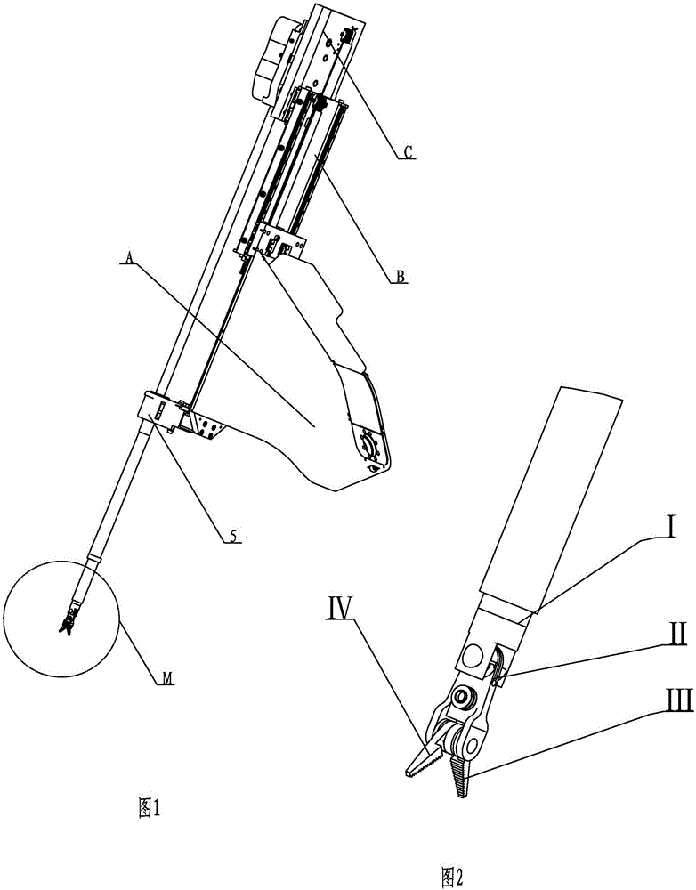
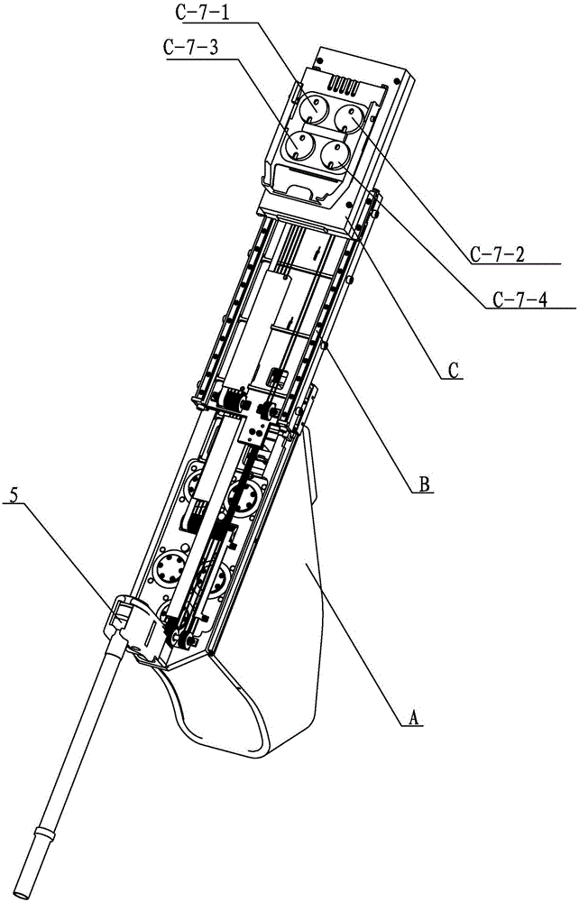
[0022] Specific implementation mode one: combine Figure 1-Figure 49 Describe this embodiment. This embodiment includes a vertical translation safety braking device, a passive joint P2, a first joint K1, a second joint K2 and an integrated surgical instrument drive device. One end of the passive joint P2 is rotatably mounted on the vertical translation On the upper part of the safety brake device, one end of the first joint K1 is rotatably connected to the passive joint P2, one end of the second joint K2 is rotatably connected to the other end of the first joint K1, and the integrated surgical instrument drive device is installed on the second The other end of the joint K2, the vertical translation safety braking device includes a base assembly 1, a guide rail assembly 2 and an outer end interface connector 3; the base assembly 1 includes a box body 1-1, a counterweight 1-2 and at least one Optical axis assembly, at least one optical axis assembly is arranged on the box body 1...

specific Embodiment approach 2

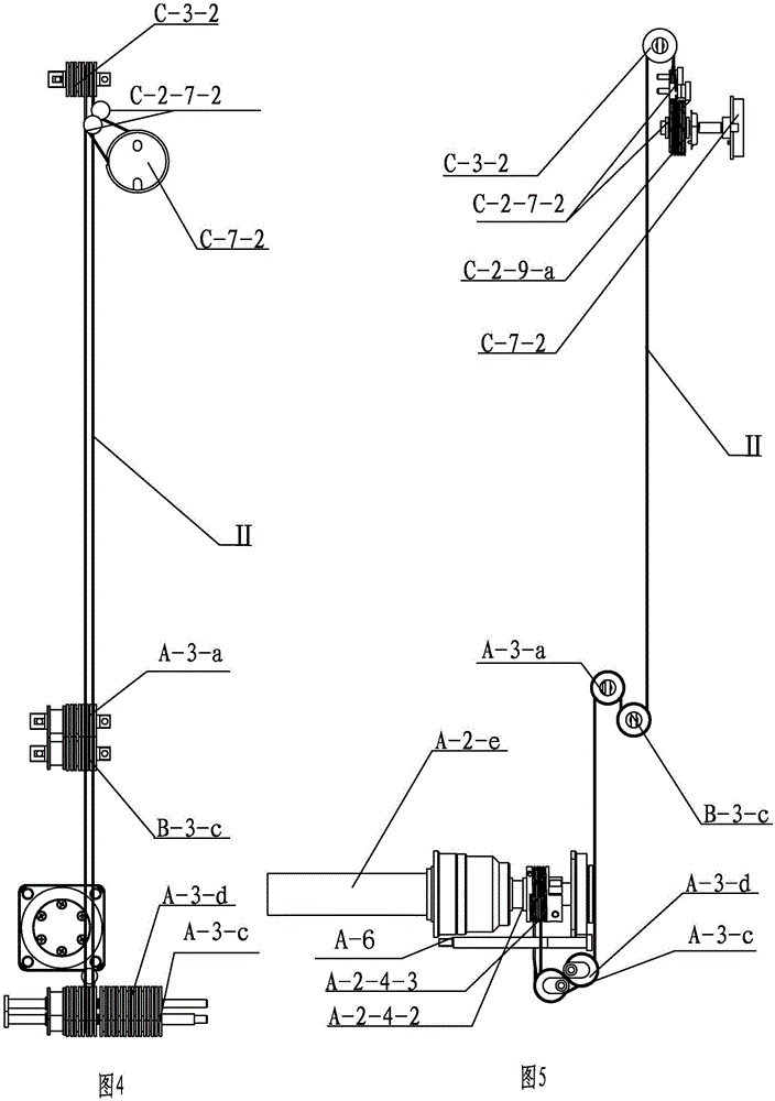
[0027] Specific implementation mode two: combination Figure 19 Explain that the power source assembly A of this embodiment also includes a power source cover A-5, a driver A-8, a guide shaft A-6 and a winding wire fixing assembly A-7 at the power source, and the power source cover A-5 Covered on the drive support frame A-1 and multiple drive components A-2, the winding wire fixing component A-7 at the power source is installed on the drive support plate A-1, the driver A-8 and the guide shaft A-6 are installed On drive support frame A-1. With this embodiment set up in this way, the power supply is more stable. The undisclosed technical features in this embodiment are the same as those in the first embodiment.

specific Embodiment approach 3

[0028] Specific implementation mode three: combination Figure 23 and Figure 33 Explain that the drive assembly A-2 of this embodiment includes five motor drive assemblies, respectively the first motor drive assembly A-2-a, the second motor drive assembly A-2-b, the third motor drive assembly A-2- c. The fourth motor drive assembly A-2-d and the fifth motor drive assembly A-2-e, wherein the structures of the five motor drive assemblies are the same and different in that the helix of the second motor drive assembly A-2-b The wheel is a double wire wheel A-2-9, and the first motor drive assembly A-2-a includes a drive motor A-2-1, a motor support frame A-2-2, a harmonic reducer A-2-3, Drive spiral wheel A-2-4, drive rotation shaft A-2-5, drive spiral support block A-2-6 and drive cover A-2-7, drive motor A-2-1 is installed on the motor support frame One end of the body A-2-2, one end of the driving screw shaft A-2-5 is connected with the flex spline of the harmonic reducer A-...


PUM


Abstract

The invention provides an instrument holding mechanical arm used for a minimally-invasive robot, and relates to the instrument holding mechanical arm. The instrument holding mechanical arm solves the problems that the number of passive joints is large when an existing mechanical arm is arranged in a concentrated mode and the existing mechanical arm is large in overall size and low in rigidity when a passive arm is too long. The instrument holding mechanical arm comprises vertical horizontally-moving safety brake devices, passive joints, first joints, second joints and an integrated operative instrument drive device. One ends of the passive joints are arranged on the upper portions of the vertical horizontally-moving safety brake devices in a rotatable mode. One ends of the first joints are connected to the passive joints in a rotatable mode. One ends of the second joints are connected with the other ends of the first joints in a rotatable mode. The integrated operative instrument drive devices are arranged at the other ends of the second points. The instrument holding mechanical arm is used for operative instrument drive of the micro operative instruments of the robot.

Description

technical field [0001] The invention relates to an integrated surgical instrument driving device, in particular to a minimally invasive robotic arm holding a device, which belongs to the field of medical instruments. Background technique [0002] At present, minimally invasive surgery is a hot spot in medical technology research, and it is the development trend of future surgery, mainly because minimally invasive medicine has many advantages: such as less trauma, shorter hospital stay, faster recovery, and fewer postoperative complications. However, traditional endoscopic surgery has many disadvantages, such as low operation accuracy, small field of view, small degree of freedom of operation, and doctors are prone to fatigue and trembling; with the development of science and technology, robotic medical assistance technology can well solve these problems. Robot-assisted technology can provide a 3D field of view, which is convenient for doctors to operate. Micro medical device...

Claims


Application Information

Patent Timeline
Patent Type & Authority Applications(China)
IPC IPC(8): A61B19/00
Inventor 付宜利潘博牛国君张福海封海波王树国
Owner HARBIN INST OF TECH
Why Eureka
Try Eureka