

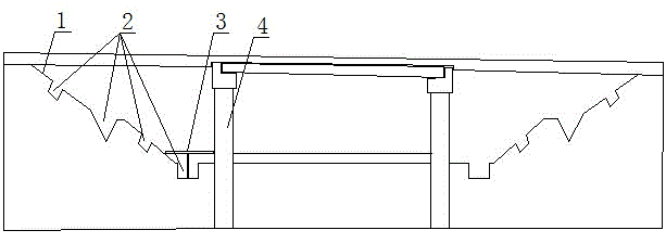
Bridge span reduction method and special-purposed bridge span reduction backfill material
A technology of bridges and mixed materials, applied in the field of bridge span reduction and special bridge span reduction backfill material, can solve the problems of incapable of solving the problem of jumping at the bridge head, much maintenance in the later period, and poor economy, and achieves the reduction of density, good effect, and good use. handy effect
- Summary
- Abstract
- Description
- Claims
- Application Information
AI Technical Summary
Problems solved by technology
Method used
Image

Examples
Embodiment 1
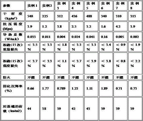
[0053] A special bridge span reduction and backfill material, comprising the following components by weight: cement: 350 parts, mixed material: 80 parts, water: 120 parts, regulator: 35 parts, foaming agent: 10 parts, microfoaming agent: 6 parts, waterproofing agent: 5 parts.
[0054] The mixed material in this example includes granulated blast furnace slag.
[0055] The conditioner in this embodiment includes water reducer, rubber powder, reinforcing agent and foam stabilizer.
[0056] Foaming agent is coconut acid diethanolamide in the present embodiment.
[0057] The cement used in this example is PC42.5 cement, and the microfoaming agent is prepared by diluting the foaming agent and water at a ratio of 1:2000 and microfoaming by a plunger pump.
[0058] The waterproofing agent described in this embodiment includes an inorganic aluminum salt waterproofing agent.
Embodiment 2
[0060] A special bridge span reduction and backfill material, comprising the following components by weight: cement: 220 parts, mixed material: 40 parts, water: 180 parts, regulator: 40 parts, foaming agent: 14 parts, microfoaming agent: 8 parts, waterproofing agent: 5 parts.
[0061] The mixed material in this embodiment includes coal gangue.
[0062] The conditioner in this embodiment includes water reducer, rubber powder, reinforcing agent and foam stabilizer.
[0063] In this embodiment, the foaming agent is liquid silica gel.
[0064]The cement used in this example is PC42.5 cement, and the microfoaming agent is prepared by diluting the foaming agent and water at a ratio of 1:2000 and microfoaming by a plunger pump.
[0065] The waterproofing agent described in this embodiment includes an inorganic aluminum salt waterproofing agent.
Embodiment 3
[0067] A special bridge span reduction and backfill material, comprising the following components by weight: cement: 300 parts, mixed material: 70 parts, water: 150 parts, regulator: 35 parts, foaming agent: 15 parts, microfoaming agent: 7 parts, waterproofing agent: 6 parts.
[0068] The mixed material in this embodiment includes carbide slag.
[0069] The conditioner in this embodiment includes water reducer, rubber powder, reinforcing agent and foam stabilizer.
[0070] In this embodiment, the foaming agent is coconut acid diethanolamide: the ratio of liquid silica gel is 2:1.
[0071] The cement used in this example is PC42.5 cement, and the microfoaming agent is prepared by diluting the foaming agent and water at a ratio of 1:2000 and microfoaming by a plunger pump.
[0072] The waterproofing agent described in this embodiment includes an inorganic aluminum salt waterproofing agent.
PUM
 Abstract
Description
Claims
Application Information