Multifunctional component gas fatigue test system

A fatigue test and component technology, applied in the field of test systems, can solve problems such as inability to perform high and low temperature tests, inability to test other components, and lack of temperature control devices, etc., to increase the scope of application, reduce test costs, and ensure safety. Effect

Active Publication Date: 2015-11-04
ZHEJIANG UNIV
View PDF12 Cites 13 Cited by
  • Summary
  • Abstract
  • Description
  • Claims
  • Application Information

AI Technical Summary

Problems solved by technology

Except for the cylindrical spring, this device cannot test other components, and the pressure output is relatively s

Method used


Image

  • Multifunctional component gas fatigue test system

Examples


Embodiment 1

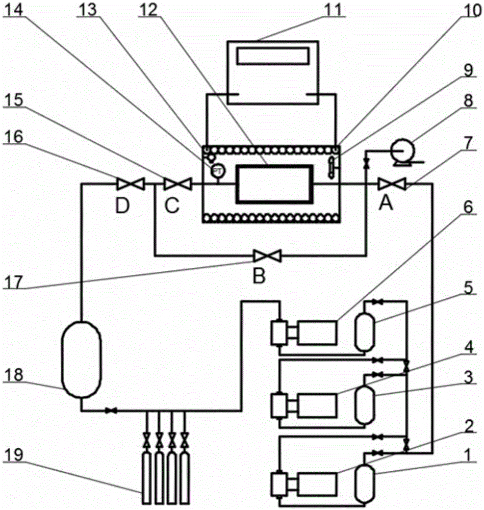
[0034] In this embodiment, the cycle test is carried out by taking the shut-off valve in the 70MPa vehicle-mounted hydrogen fuel cell system as an example. The test pressure is 2MPa to 87.5MPa, and the supercharger is selected as the first-stage supercharger 6, the second-stage supercharger 4 and the third-stage supercharger 2. The test process is as follows: install test stop valve 12, open all valves and use vacuum pump 8 to vacuumize. Close the valve D 16, open the gas cylinder 19, and the gas flows through the first-stage booster 6, the first-stage buffer tank 5, the second-stage booster 4, the second-stage buffer tank 3, the third-stage booster 2, and the third-stage buffer tank 1. Finally, it enters both sides of the stop valve through stop valve A 7, stop valve B 17, and stop valve C 15. When releasing the pressure, close the shut-off valve A7, open the shut-off valve D16, the gas flows out from both sides of the shut-off valve and enters the recovery tank 18, completi...

Embodiment 2

[0036] In this embodiment, the cycle test is carried out by taking the hydride hydrogen storage cylinder 19 as an example. The test pressure is 0.1MPa to 1.0MPa, and the supercharger is selected from the first-stage supercharger 6 and the second-stage supercharger 4 . The test process is as follows: install test gas cylinder 19, open all valves and vacuumize with vacuum pump 8. Close the shut-off valve B 17, shut-off valve C 15, shut-off valve D 16, open the gas cylinder 19, the gas flows through the primary supercharger 6, the primary buffer tank 5, the secondary supercharger 4, the secondary buffer tank 3, Finally, it enters the gas cylinder 19 through the shut-off valve A 7 . When releasing pressure, close the shut-off valve A 7, open the shut-off valve B 17 and the shut-off valve D 16, the gas flows out from the gas cylinder 19 and enters the recovery tank 18, completing a cycle. After some cycles finished, when carrying out second gas cylinder 19 tests, only need close ...


PUM


Abstract

The invention relates to the field of test systems, and aims to provide a multifunctional component gas fatigue test system. The multifunctional component gas fatigue test system includes a supercharging device, a recovery tank, a gas cylinder, a refrigeration heating machine, a high-low temperature environment box, an anti-explosion fan, a gas leakage detector, a vacuum pump, stop valves and a control system, and can perform a gas tightness test, a fatigue test and the like on a test component. The multifunctional component gas fatigue test system provided by the invention realizes a function of a gas cycle fatigue test of a component, and can perform a pressure maintaining test and fatigue test and the like; realizes reutilization of tail gas, thereby reducing test cost; realizes testing of a large pressure range, thereby satisfying requirements of different component test pressure; realizes isolation of a heat exchange medium and test gas, thereby guaranteeing safety of a device and personnel, and improves heat exchange efficiency through the environment box and the anti-explosion fan; and realizes testing functions of various components, thereby increasing the range of application of the test device.

Description

technical field [0001] The invention relates to the field of test systems, in particular to a gas fatigue test system for multifunctional components. Background technique [0002] Gaseous energy sources such as hydrogen and natural gas are widely used in industry and life, and their operating pressures range from atmospheric pressure to tens of megapascals. The gas cylinders and valves storing these gases will be repeatedly charged and discharged during use, resulting in repeated changes in stress and temperature, resulting in damage, deterioration of the performance of the gas cylinders and valves, and even cracks. In addition, in a high-pressure environment, hydrogen can also lead to deterioration of the mechanical properties of some metal materials. Therefore, UN-GTR 13, ANSI NGV2-2007 and other standards require the use of stored gas for cycle testing to ensure safe and stable operation of the product within the design life. [0003] Different from gas cylinders, parts...

Claims


Application Information

Patent Timeline
IPC IPC(8): G01M13/00
Inventor 郑津洋崔天成顾超华张俊峰郭进兴刘鹏飞赵永志黄改
Owner ZHEJIANG UNIV
Why Eureka
Try Eureka