
Magnetic assembly with multi-air-gap

A technology of magnetic components and air gaps, applied in the field of magnetic components with multiple air gaps, can solve the problems of temperature rise of inductance components 1, reduction of winding utilization rate, high temperature, etc.

Inactive Publication Date: 2015-11-04
DELTA ELECTRONICS INC
View PDF3 Cites 1 Cited by
  • Summary
  • Abstract
  • Description
  • Claims
  • Application Information

AI Technical Summary

Problems solved by technology

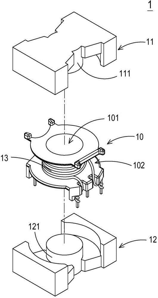
However, the setting of the winding frame 10 will occupy a certain space, resulting in a reduction in the number of winding groups that can be accommodated between the first magnetic core 11 and the second magnetic core 12, reducing the utilization rate of the winding wires, and it is impossible to increase the number of winding wires. The wire diameter of the group will cause the overall temperature of the inductance component 1 to be too high, reducing the working efficiency of the inductance component 1
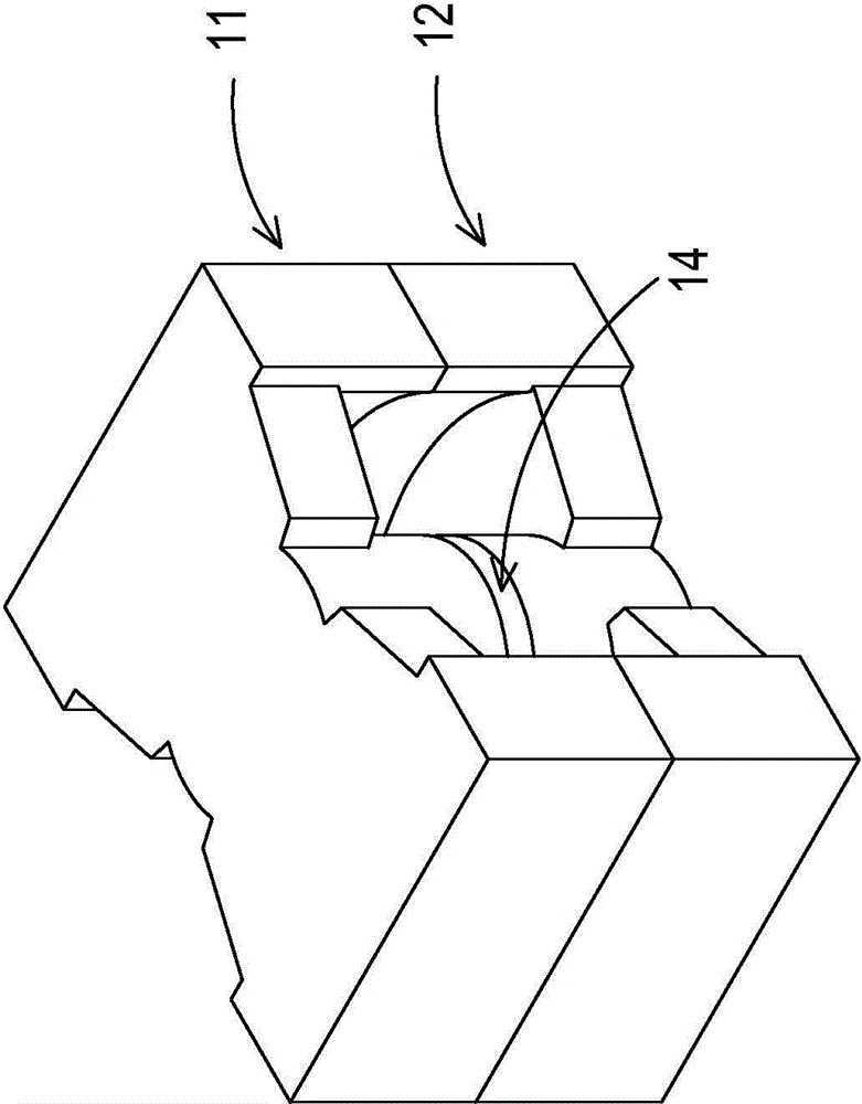
In addition, the existing inductance component 1 utilizes the single air gap 14 formed between the center column 111 of the first magnetic core 11 and the center column 121 of the second magnetic core 12 to avoid magnetic saturation, however, the larger the air gap will be Causes higher flux leakage, leads to increased energy consumption, increases the overall temperature of the inductance component 1, and reduces the working efficiency of the inductance component 1
[0004] Therefore, how to solve the problems faced by the traditional air-gapped inductance components such as the low utilization rate of the winding group, the inability to increase the diameter of the winding wire, the high overall temperature of the inductance component and the inability to improve the efficiency, etc., is an issue to be solved at present.

Method used


Image

  • Magnetic assembly with multi-air-gap
  • Magnetic assembly with multi-air-gap
  • Magnetic assembly with multi-air-gap

Examples


Embodiment Construction

[0054] In order to make the purpose, technical solutions and advantages of the embodiments of the present invention clearer, the technical solutions in the embodiments of the present invention will be clearly and completely described below in conjunction with the drawings in the embodiments of the present invention. Obviously, the described embodiments It is a part of embodiments of the present invention, but not all embodiments. Elements and features described in one drawing or one embodiment of the present invention may be combined with elements and features shown in one or more other drawings or embodiments. It should be noted that representation and description of components and processes that are not related to the present invention and known to those of ordinary skill in the art are omitted from the drawings and descriptions for the purpose of clarity. Based on the embodiments of the present invention, all other embodiments obtained by persons of ordinary skill in the ar...


PUM


Abstract

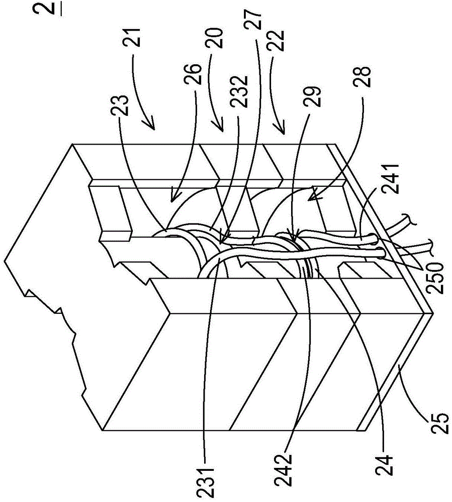
The invention relates to a magnetic assembly with multi-air-gap. The magnetic assembly comprises a first magnetic core, a second magnetic core, a middle-layer magnetic core, a first winding, and a second winding. The middle-layer magnetic core is arranged between the first magnetic core and the second magnetic core. The first magnetic core is coupled with the middle-layer magnetic core and a first winding space and a first air gap are formed. The second magnetic core is coupled with the middle-layer magnetic core and a second winding space and a second air gap are formed. The first winding is winded in the first winding space and covers the first air gap. The second winding is winded in the second winding space and covers the second air gap. The first winding and the second winding are connected in series. A reel is not needed, and wires are directly winded on the magnetic cores. Thus, manufacturing cost is reduced, and winding usage rate is improved. Through dispersed distribution and arrangement of the multi-air-gap, leakage flux loss is reduced and dispersed, and diffusion magnetic flux is reduced, so operating temperature of the magnetic assembly is reduced, thereby improving operating efficiency of the magnetic assembly.

Description

technical field [0001] The invention relates to a magnetic assembly, in particular to a magnetic assembly with multiple air gaps. Background technique [0002] Generally speaking, magnetic components such as transformers and inductance components are often used in various electrical equipment. For an example of inductive components, see Figure 1A and Figure 1B , Figure 1A is a schematic diagram of the explosive structure of an existing inductive component with an air gap, and Figure 1B for Figure 1A A partial structural schematic diagram of the inductance component, wherein the winding frame and the winding group are omitted in the figure and not shown. The inductance component 1 with an air gap can be applied to a power factor correction circuit of a power supply device or an inductance component of a resonant circuit, and includes a bobbin 10, a first magnetic core 11, a second magnetic core 12 and a winding group 13 . The bobbin 10 has a through channel 101 and a...

Claims


Application Information

Patent Timeline
IPC IPC(8): H01F17/04H01F27/24H01F27/30
Inventor 陈义霖陈坤德刘梵麟洪楀量林汉星刘建宏
Owner DELTA ELECTRONICS INC
Learn More