

DRAM with SDRAM interface, and hybrid flash memory module
A memory module, memory technology, applied in static memory, memory system, digital memory information and other directions, can solve problems such as inability to meet, and achieve the effect of increasing processing capacity
- Summary
- Abstract
- Description
- Claims
- Application Information
AI Technical Summary
Problems solved by technology
Method used
Image



Examples
Embodiment approach
[0044] Figure 14It is a figure which shows the structure of the memory module concerning an embodiment. The memory module 60 has a substrate 61 , socket terminals 62 , a plurality of high-speed memories 63 , a plurality of nonvolatile memories 64 which are mass memories having a storage capacity larger than the high-speed memories, and a plurality of controllers 65 . The controller 65 is mounted on the socket terminal 62 side of the first surface of the substrate 61 , and the high-speed memory 63 is mounted on the second surface of the substrate 61 . The nonvolatile memory 64 is mounted at a position away from the socket terminal 62 . In other words, the nonvolatile memory 64 is mounted on the side opposite to the socket terminal 62 with respect to the controller 65 . Furthermore, the nonvolatile memory 64 is mounted on the side opposite to the socket terminal 62 with respect to the high speed memory 63 .
[0045] With the above configuration, the controller 65 and the hig...
Embodiment
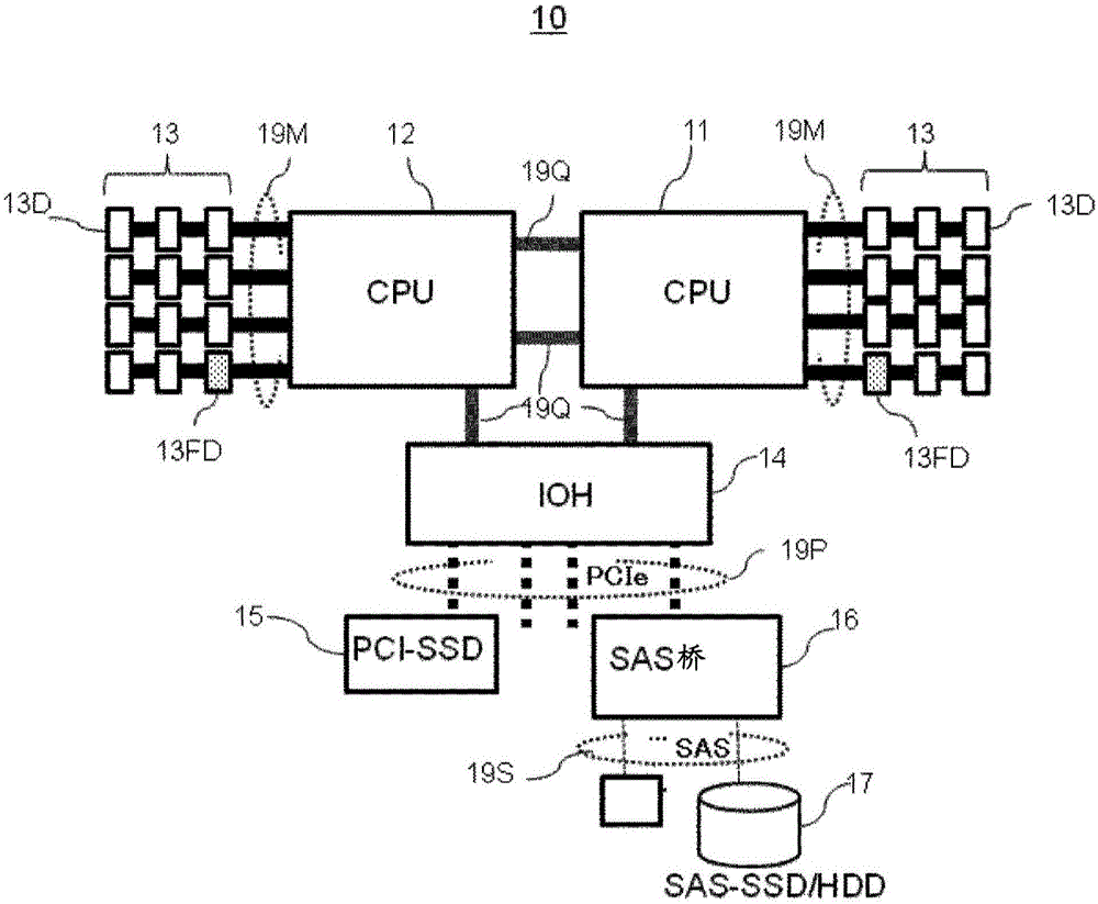
[0047] In this embodiment, a server is described as an example of an information processing device, but it is also applicable to an information processing device other than a server, such as a PC (Personal Computer). Furthermore, although a memory module with ECC is described as an example of a memory module, it is also applicable to a memory module without ECC. In addition, SDRAM (DRAM) is used as an example of the high-speed memory for description, but the high-speed memory may also be, for example, MRAM (Magnetic Random Access Memory, Magnetic Random Access Memory), STT (Spin Transfer Torque, spin torque)-RAM, phase change memory, etc. In addition, SDRAM is also an example of a volatile semiconductor memory that cannot store data when the power is turned off. A flash memory will be described as an example of a nonvolatile memory, but it is not limited thereto, and any semiconductor memory may be used as long as it can store data even when the power is turned off, and can s...
Deformed example 1
[0117] Figure 10 is a diagram showing the component arrangement of the hybrid memory module according to Modification 1. Figure 10 (a) represents the surface of the memory module, Figure 10 (b) shows the back side of the hybrid memory module. In DIMM 50A according to Modification 1, data memory controller (MCD) 21D and SDRAM (DRAM) 22S are alternately arranged on the front and back of substrate 51 . The configuration of the address memory controller (MAC) 21A, the flash memory (Flash) 23F, the SPD 31, and the socket terminal 52 is the same as that of the memory module 50 according to the embodiment. Since there are many wires between the data memory controller (MCD) 21D and the flash memory (Flash) 23F, it is possible to generate ample wiring by alternately setting the data memory controller (MCD) 21D and SDRAM (DRAM) 22S .
[0118] In addition, in Figure 10 In the above, five data memory controllers (MCD) 21D and four SDRAM (DRAM) 22S are arranged on the surface of t...
PUM
 Abstract
Description
Claims
Application Information