Rotary type galvanometer scanning device and application method thereof

A galvanometer scanning and rotating device technology, applied in welding equipment, laser welding equipment, metal processing equipment, etc., can solve the problems of high technical content, high cost, increased hardware control and software complexity, etc., to overcome the limitation of working space , expanding the scope of work, avoiding the effect of system complexity and hardware cost increase

Inactive Publication Date: 2015-11-11
FUJIAN INST OF RES ON THE STRUCTURE OF MATTER CHINESE ACAD OF SCI
View PDF8 Cites 5 Cited by
  • Summary
  • Abstract
  • Description
  • Claims
  • Application Information

AI Technical Summary

Problems solved by technology

However, scanning galvanometers are components with high technical content and high cost in rapid prototyping equipment. The use of multiple scanning galvanometers not only greatly increases the complexity of hardware control and software, reduces the working stability of the system, but also greatly increases the System hardware cost

Method used


Image

  • Rotary type galvanometer scanning device and application method thereof
  • Rotary type galvanometer scanning device and application method thereof

Examples


Embodiment Construction

[0015] The present invention will be further described below in conjunction with the accompanying drawings.

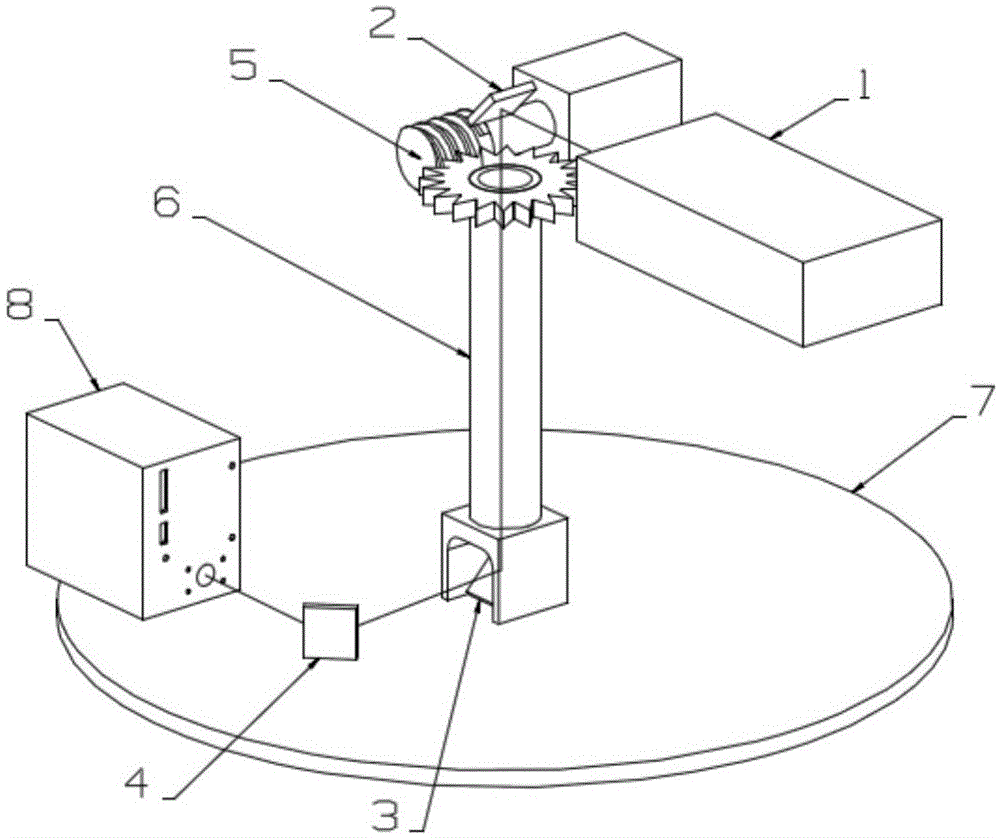
[0016] Such as figure 1 As shown, a rotary galvanometer scanning device provided by the present invention includes a laser 1 , laser propagation devices 2 , 3 , 4 , a rotating device 5 , a rotating shaft 6 , a turntable 7 and a scanning galvanometer 8 .

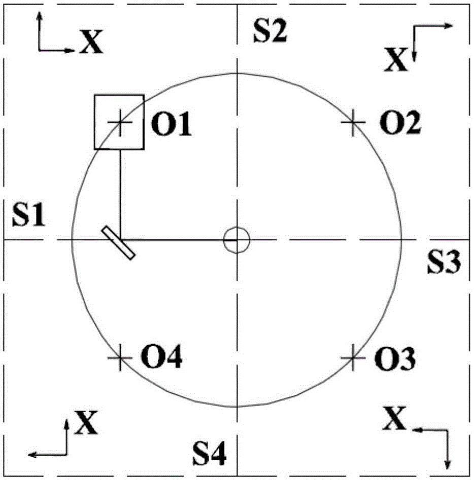
[0017] The turntable 7 is disc-shaped, the scanning vibrating mirror 8 is installed on the turntable 7, the first end of the rotating shaft 6 is connected to the center of one side of the turning table 7, and the rotating device 5 drives the rotating shaft 6 to rotate, so that the scanning vibrating mirror 8 follows the turntable 7 Turn together to change its working position. The laser light emitted by the laser 1 is reflected by the laser propagation devices 2 , 3 , 4 and the scanning galvanometer 8 , and irradiates the working surface below the scanning galvanometer 8 .

[0018] The rotating device 5 is composed ...


PUM


Abstract

The invention discloses a rotary type galvanometer scanning device. The rotary type galvanometer scanning device comprises a laser apparatus, a rotating device, a rotating shaft, a rotary table and a scanning galvanometer. The scanning galvanometer is installed on the rotary table. The first end of the rotating shaft is connected to one side of the rotary table. The rotating shaft is driven by the rotating device to rotate, the scanning galvanometer accordingly rotates together with the rotary table, and the working position of the scanning galvanometer is changed. The invention further provides an application method of the rotary type galvanometer scanning device. The rotary type galvanometer scanning device has four fixed working positions within a 360-degree circumference range, the working range of the scanning galvanometer is accordingly expanded by four times on the premise that the scanning galvanometer guarantees the machining accuracy, the working space limitation caused by the fixing mode of the scanning galvanometer is overcome, and meanwhile the problem that due to a multi-scanning-galvanometer working mode, the system complexity and the hardware cost are increased is solved.

Description

technical field [0001] The invention belongs to the field of laser rapid prototyping, and in particular relates to a rotary vibrating mirror scanning device and an application method thereof. Background technique [0002] Rapid prototyping technology, also known as rapid prototyping manufacturing (RPM) technology, was born in the late 1980s. It is a high-tech manufacturing technology based on material accumulation method and is considered to be a major achievement in the manufacturing field in the past 20 years. It integrates mechanical engineering, CAD, reverse engineering technology, layered manufacturing technology, numerical control technology, material science, and laser technology. It uses 3D CAD data to accumulate layers of materials into physical prototypes through rapid prototyping machines. [0003] According to the molding method, rapid prototyping technology can be divided into Fused Deposition Modeling (FDM), Selective Laser Melting Modeling (SLM), Stereolithogr...

Claims


Application Information

Patent Timeline
Patent Type & Authority Applications(China)
IPC IPC(8): B23K26/082
Inventor 黄见洪林文雄张志史斐郑晖葛燕吴鸿春戴殊韬
Owner FUJIAN INST OF RES ON THE STRUCTURE OF MATTER CHINESE ACAD OF SCI
Why Eureka
Try Eureka