Device and method for recovering disulfide from condensate oil desulfurized alcohol and alkali liquor

A technology for disulfide and desulfurization, which is applied in the field of devices for desulfurization of condensate and regeneration of lye to recover disulfides, can solve the problem of large consumption of alkali residues and discharge of alkali residues, corrosion of condensate oil fractionation devices, Problems such as corrosion of downstream condensate processing equipment

Active Publication Date: 2015-11-11
NINGBO ZHONGYI PETROCHEM TECH
View PDF5 Cites 8 Cited by
  • Summary
  • Abstract
  • Description
  • Claims
  • Application Information

AI Technical Summary

Problems solved by technology

[0002] Condensate oil with a distillation range of 30°C-210°C generally contains a small amount of H 2 S, and hundreds or even thousands of ppm of sulfides, mercaptans, thiophenes and other sulfides, among which the mercaptan content accounts for more than 70% of the total sulfur, and the carbon three and below mercaptans account for more than 80% of the total mercaptans , and due to the strong toxicity, volatility, corrosiveness and disgusting odor of mercaptans, the corrosion of condensate oil processing equipment is serious, and at the same time, it has a great impact on environmental pollution
[0003] At present, for the processing of condensate oil, some refineries adopt the method of direct fractionation to obtain the products of each fraction, and then desulfurize the products of each

Method used


Image

  • Device and method for recovering disulfide from condensate oil desulfurized alcohol and alkali liquor
  • Device and method for recovering disulfide from condensate oil desulfurized alcohol and alkali liquor
  • Device and method for recovering disulfide from condensate oil desulfurized alcohol and alkali liquor

Examples


Embodiment 1

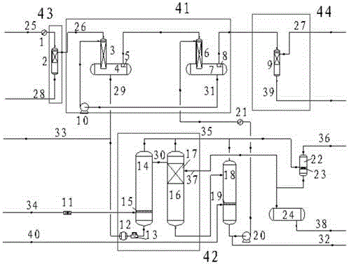
[0085] Such as figure 1 As shown, the condensate oil enters the device through the feed pipe 25, and the condensate oil feed pipe 25 is connected to the condensate oil filter 1 and the coalescence dehydrator 2, and the condensate oil is filtered through the condensate oil filter 1 to remove mechanical impurities, The entrained water is removed through the coalescing dehydrator 2, the oily sewage pipe 28 is connected to the bottom of the coalescing dehydrator 2, and the coalescing dehydrator 2 is connected to the first-stage liquid film contactor 3 through the condensate oil connecting pipe 26, and the first-stage liquid film contactor 3 The contactor 3 is installed on the primary sweetening separation tank 4 through a flange, and the top of the primary sweetening separation tank 4 has a condensate oil outlet, and the condensate oil outlet is provided with a first-stage sweetening separation tank condensate oil outlet stop in the tank Plate 5, the condensate oil outlet is conne...

Embodiment 2

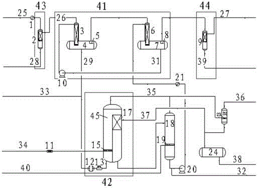
[0087] Such as figure 2 As shown, the condensate oil enters the device through the condensate oil feed pipe 25, and the condensate oil feed pipe 25 is connected to the condensate oil filter 1 and the coalescence dehydrator 2, and the condensate oil is filtered and removed by the condensate oil filter 1 Mechanical impurities are removed from the entrained water through the coalescing dehydrator 2. The oily sewage pipe 28 is connected to the bottom of the coalescing dehydrator 2. The coalescing dehydrator 2 is connected to the first-stage liquid film contactor 3 through the condensate oil connecting pipe 26. The first-stage liquid film contactor 3 is installed on the first-stage sweetening separation tank 4 through a flange, and the top of the first-stage sweetening separation tank 4 has a condensate oil outlet, and the condensate oil outlet is provided with a baffle 5 in the tank, and the condensate oil The outlet is connected to the secondary liquid film contactor 6 through t...

Embodiment 3

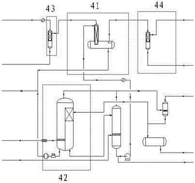
[0089] Such as Figure 9As shown, the condensate oil enters the device through the feed pipe 25, and the condensate oil feed pipe 25 is connected to the condensate oil filter 1 and the coalescence dehydrator 2, and the condensate oil is filtered through the condensate oil filter 1 to remove mechanical impurities, The entrained water is removed through the coalescing dehydrator 2, the oily sewage pipe 28 is connected to the bottom of the coalescing dehydrator 2, and the coalescing dehydrator 2 is connected to the first-stage liquid film contactor 3 through the condensate oil connecting pipe 26, and the first-stage liquid film contactor 3 The contactor 3 is installed on the primary sweetening separation tank 4 through a flange. There is a condensate oil outlet on the top of the primary sweetening separation tank 4. The condensate oil outlet is provided with a baffle 5 in the tank. The condensate oil outlet passes through the condensate The oil analysis connecting pipe 26 is conn...


PUM


Abstract

The invention relates to a device for recovering disulfide from condensate oil desulfurized alcohol and alkali liquor, which comprises a desulfurized alcohol treatment unit, wherein a bottom end outlet of the desulfurized alcohol treatment unit is communicated with a bottom end inlet of an alkali liquor oxidization and sulfur dioxide separation unit; a bottom end outlet of the alkali liquor oxidization and sulfur dioxide separation unit is communicated with a side end inlet of an alkali liquor gas stripping column; a top end outlet of the alkali liquor oxidization and sulfur dioxide separation unit and a top end outlet of the alkali liquor gas stripping column are respectively communicated with a side end inlet of an exhaust water washing dealkalization tank; a side end outlet of the alkali liquor oxidization and sulfur dioxide separation unit and a bottom end outlet of the exhaust water washing dealkalization tank are respectively communicated with a top end inlet of a disulfide tank; a bottom end outlet of the alkali liquor gas stripping column is communicated with a side end inlet of the desulfurized alcohol treatment unit; and the device also comprises one or a plurality of filters connected in the components above, a plurality of circulating pumps, a plurality of pipelines, a plurality of liquid inlets and a plurality of liquid outlets.

Description

technical field [0001] The invention relates to condensate oil treatment equipment, in particular to a device and method for sweetening condensate oil and regenerating lye to recover disulfide. Background technique [0002] Condensate oil with a distillation range of 30°C-210°C generally contains a small amount of H 2 S, and hundreds or even thousands of ppm of sulfides, mercaptans, thiophenes and other sulfides, among which the mercaptan content accounts for more than 70% of the total sulfur, and the carbon three and below mercaptans account for more than 80% of the total mercaptans , and due to the strong toxicity, volatility, corrosiveness and disgusting odor of mercaptans, the corrosion of condensate oil processing equipment is serious, and at the same time, it has a great impact on environmental pollution. [0003] At present, for the processing of condensate oil, some refineries adopt the method of direct fractionation to obtain the products of each fraction, and then...

Claims


Application Information

Patent Timeline
IPC IPC(8): C10G53/12
Inventor 喻武钢聂通元王铭蔡喜洋
Owner NINGBO ZHONGYI PETROCHEM TECH
Why Eureka
Try Eureka