Roller bottom type saw web quenching line

A roller bottom type, saw blade technology, applied in the direction of quenching agent, quenching device, furnace type, etc., can solve problems such as failure to achieve mechanical properties, and achieve the effects of convenient equipment maintenance, improved water utilization, and long life.

Inactive Publication Date: 2015-11-11
QUANZHOU HAIENDE ELECTROMECHANICAL TECH DEV
View PDF1 Cites 6 Cited by
  • Summary
  • Abstract
  • Description
  • Claims
  • Application Information

AI Technical Summary

Problems solved by technology

So far, old equipment such as trolley furnace + quenching pool, pit furnace + quenching pool have been used, and the mechanical properties after heat treatment that meet international standards cannot be achieved.

Method used


Image

  • Roller bottom type saw web quenching line
  • Roller bottom type saw web quenching line
  • Roller bottom type saw web quenching line

Examples


Embodiment 1

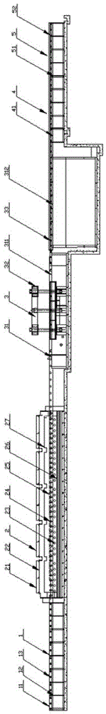
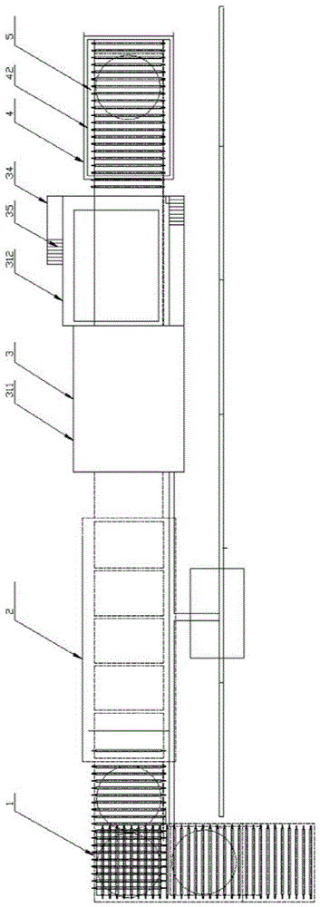
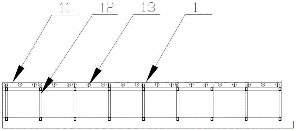
[0020] refer to Figure 1-Figure 6 , a roller bottom type saw blade quenching line, comprising a feeding table 1, a heating furnace 2, an automatic quenching and flattening system 3, a discharge cleaning tank 4 and a discharge table 5 connected in sequence, and the feed table 1 is composed of a shell Body 11, section steel welding forming frame 12 and feed roller 13, bearings and bearing seats are installed horizontally on both sides of feed roller 13 to ensure that the workpiece runs smoothly and does not run sideways. The heating furnace 3 is mainly composed of furnace Shell 21, furnace lining 22, radiant tube electric heating element 23, driving roller 24, transmission mechanism 25, protective atmosphere pipeline system 26 and uniform fan 27, the driving roller 24 is set in the furnace shell 21 for supporting and Convey the workpiece, and horizontally level the drive roller 24 on the same level. The automatic quenching and flattening system 3 is mainly composed of an oil ta...

Embodiment 2

[0023] refer to Figure 1-Figure 6 , a roller bottom type saw blade quenching line, comprising a feeding table 1, a heating furnace 2, an automatic quenching and flattening system 3, a discharge cleaning tank 4 and a discharge table 5 connected in sequence, and the feed table 1 is composed of a shell Body 11, section steel welding forming frame 12 and feed roller 13, bearings and bearing seats are installed horizontally on both sides of feed roller 13 to ensure that the workpiece runs smoothly and does not run sideways. The heating furnace 3 is mainly composed of furnace Shell 21, furnace lining 22, radiant tube electric heating element 23, driving roller 24, transmission mechanism 25, protective atmosphere pipeline system 26 and uniform fan 27, the driving roller 24 is set in the furnace shell 21 for supporting and Convey the workpiece, and horizontally level the drive roller 24 on the same level. The automatic quenching and flattening system 3 is mainly composed of an oil ta...


PUM


Abstract

The invention discloses a roller bottom type saw web quenching line. The quenching line comprises a feeding table, a heating furnace, an automatic quenching flattening system, a discharged material cleaning tank and a discharging table which are connected in sequence. The heating furnace is mainly composed of a furnace shell, a furnace lining, a radiant tube electric heating element, transmission carrier rollers, a delivery mechanism, a protective atmosphere pipeline system and a homogenizing fan, wherein the transmission carrier rollers are arranged in the furnace shell and used for supporting and delivering workpieces, and the transmission carrier rollers are leveled horizontally to be located on the same horizontal plane. The automatic quenching flattening system is mainly composed of an oil groove, a press, a deoiling rubber roller device and an external auxiliary oil tank, wherein the oil groove comprises a main oil groove part and an auxiliary oil groove part, the main oil groove part and the auxiliary oil groove part are provided with two filter screens, and the press comprises an upper pressure plate and a lower pressure plate. The discharged material cleaning tank is a cuboid cleaning water tank formed by tight welding of sheet steel and sectional steel, and a sprinkling pipe is arranged on top of the cleaning water tank. According to the production line, interval continuous operation is adopted from feeding to discharging, equipment maintenance is convenient and safe, heating transmission and quenching flattening are conducted in different stages, and production efficiency is improved.

Description

technical field [0001] The invention relates to the technical field of quenching equipment, in particular to a roller bottom type saw blade quenching line. Background technique [0002] Steel or non-ferrous metals are inseparable from heat treatment in the process of processing and finally forming industrial products. To develop a suitable heat treatment process requires the corresponding heat treatment equipment to achieve. As my country is transforming from a big steel producing country to a strong steel country, the lack of sophisticated heat treatment equipment will greatly restrict the extension of my country's steel industry to the high end, and cannot meet the needs of the machinery industry, oil and gas industry, and national defense industry. Especially in the field of heat treatment for oil drill collars, deep oil well pipes, mandrels, ship shafts, aircraft pipes, saw blades, military pipes, etc., our country has been lagging behind. So far, old equipment such as...

Claims


Application Information

Patent Timeline
Patent Type & Authority Applications(China)
IPC IPC(8): C21D9/24C21D1/63C21D1/58C21D1/673
Inventor 林智敏
Owner QUANZHOU HAIENDE ELECTROMECHANICAL TECH DEV
Why Eureka
Try Eureka