Calibration method for line-structured light sensor based on mechanical movement and device

A technology of linear structured light and calibration method, applied in the field of measurement, can solve the problems of low precision, complicated methods, and many artificial adjustment links.

Inactive Publication Date: 2015-11-11
HEBEI UNIV OF TECH
View PDF9 Cites 28 Cited by
  • Summary
  • Abstract
  • Description
  • Claims
  • Application Information

AI Technical Summary

Problems solved by technology

Due to the sawtooth reflection, the accuracy of the image points extracted by this method is poor, and external equipment is required to strictly adjust the light plane to be perpendicular to a certain reference plane, which is not suitable for on-site calibration; the second is the mechanical adjustment method
However, this method has many artificial adjustment links and the accuracy is not high.
The third is the filament scattering method, but the accuracy of this method is not high and the calibration process is more complicated. The fourth is the planar target method based on free movement, which is more commonly used
This method needs to solve nonlinear equations with constraints, and introduces nonlinear optimization. The method is complicated, slow, sensitive to initial value selection and noise, and cannot guarantee that the parameters converge to the global optimum.

Method used


Image

  • Calibration method for line-structured light sensor based on mechanical movement and device
  • Calibration method for line-structured light sensor based on mechanical movement and device
  • Calibration method for line-structured light sensor based on mechanical movement and device

Examples


Embodiment 1

[0041] Embodiment 1 A calibration method of a line structured light sensor based on mechanical motion,

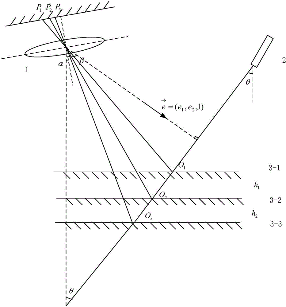
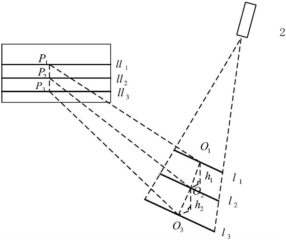
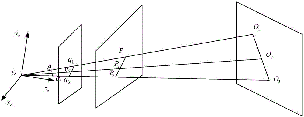
[0042] The device for performing the calibration method described in this embodiment includes a camera 1, a laser 2, a calibration plane 3, and a motion mechanism 4. The camera and the laser are installed on the motion end 41 of the motion mechanism and point to the calibration plane. The motion end can be perpendicular to the calibration plane. The plane direction moves up and down, and the camera and the laser can move synchronously in the direction perpendicular to the calibration plane. The motion mechanism also includes a guide rail 42, an encoder and a servo motor for installing the end of the motion perpendicular to the calibration plane. The camera includes a camera lens, optical filter, laser 2 is a line laser. The schematic diagram of the device is as Figure 5 shown.

[0043] In this example,

[0044] When the end of the movement moves vertically relative to t...


PUM


Abstract

The invention relates to a calibration method for a line-structured light sensor based on mechanical movement and a device. The device comprises a camera, a laser, a calibration plane and a movement mechanism. The method comprises the steps that 1) a z-axis of a world coordinate system taking the calibration plane as the ground acts as the vertical direction, an intrinsic parameter A of the camera and an extrinsic parameter of a first checkerboard are acquired by using Zhengyou Zhang checkerboard calibration, and included angle alpha between a z-axis of a camera coordinate system and the vertical direction is acquired by using the extrinsic parameter; 2) the distance between corresponding points on adjacent laser stripes and corresponding image point coordinates are calculated; 3) a normal vector of a structured light plane is solved; and 4) an included angle theta between the structured light plane and the vertical direction is calculated according to the normal vector acquired in the step 3) and the included angle alpha between the z-axis of the camera coordinate system and the vertical direction, and the coordinates of a point on the structured light plane in the camera coordinate system are further acquired so as to complete calibration for a structured light plane equation.

Description

technical field [0001] The invention belongs to the technical field of measurement and relates to the improvement of a structured light parameter calibration method. Background technique [0002] The structured light visual inspection method has the advantages of large range, non-contact, large field of view and good system flexibility. It has been widely used in industrial environments, especially in the field of welding in recent years. The calibration of structured light parameters mainly uses the internal parameters of the camera and other auxiliary tools to determine the plane equation of the light plane in the camera coordinate system. The purpose of the line structure cursor calibration is to reconstruct the three-dimensional world coordinates from the two-dimensional image coordinates to realize three-dimensional measurement. [0003] There are currently several methods for calibrating structured light sensors: one is the sawtooth target. Due to the sawtooth reflec...

Claims


Application Information

Patent Timeline
Patent Type & Authority Applications(China)
IPC IPC(8): G01B11/00
Inventor 陈海永王萌欧洋
Owner HEBEI UNIV OF TECH
Why Eureka
Try Eureka