Miniature test clamp used for disk laser device for controlling shell temperature

A technology for testing the temperature of fixtures and shells. It is applied in optical instrument testing, machine/structural component testing, temperature control, etc. It can solve the problems of increasing test time, narrow temperature control range, and large volume of water-cooled plates, and achieves the principle of the device. Simple, short temperature control time and large temperature control range

Inactive Publication Date: 2015-11-11
SHANGHAI INST OF OPTICS & FINE MECHANICS CHINESE ACAD OF SCI
View PDF5 Cites 0 Cited by
  • Summary
  • Abstract
  • Description
  • Claims
  • Application Information

AI Technical Summary

Problems solved by technology

The disadvantages of this mainly include the following points: 1. Due to the limitation of the water cooler itself (the temperature range is 5 degrees Celsius to 40 degrees Celsius), the temperature control range is too narrow, which is not conducive to accurately feeling the real working temperature of the laser tube; 2. Water cooling The heating and cooling time of the machine is slow, which greatly increases the test time; 3. The welding method increases the risk of damage to the laser due to electrostatic factors; Expand; 5. There is no corresponding temperature control indicator device, which virtually increases the probability of misoperation

Method used


Image

  • Miniature test clamp used for disk laser device for controlling shell temperature
  • Miniature test clamp used for disk laser device for controlling shell temperature
  • Miniature test clamp used for disk laser device for controlling shell temperature

Examples


Embodiment Construction

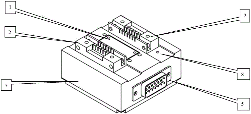
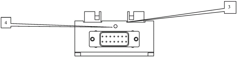
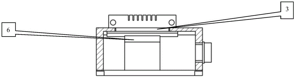
[0023] see figure 1 , figure 2 , image 3 , the whole test device consists of a set of double-row fourteen-pin butterfly laser test fixture 2, a fixture platform 7, a heat-conducting copper block 1, a standard thermistor 4, a thermal insulation gasket 3, a thermoelectric cooler 6, a It consists of DB25 pin interface 5, an LED red and green indicator light 8, a control circuit board, and an LD driving power supply. Depend on Figure 1 It can be seen that the double-row fourteen-pin dish laser fixture 2 and the heat-conducting copper block 1 (the flatness requirement is 0.02mm, the size is 30mm×13mm×2mm) are installed on the fixture platform 7 (the aluminum base, the size is 60mm) by screws ×60mm×24mm) above. Fix the heat-conducting copper block 1, the test clip heat-insulating gasket 3, and the thermoelectric cooler 6 on the fixture platform 7 through plastic screws. Note that the heat-conducting copper block 1 should not be in contact with the fixture platform 7 as much a...


PUM


Abstract

The invention provides a miniature test clamp used for a disk laser device for controlling shell temperature. The miniature test clamp comprises a set of double-row fourteen-pin disk laser device clamps, a standard thermistor, a thermoelectric refrigerating device, a thermal conducting copper block, a thermal insulation gasket, a DB25 pin interface, a red and green LED indicating lamp and a set of control circuit board. The device is compact in structure and small in size, shell temperature of the laser device can be accurately controlled and temperature control range exceeds that of a conventional water cooling device. Meanwhile, conventional welding of LD pins is substituted by pressing of the LD pins so that the power-up process of the laser device is simplified, and the risk of damage to the laser device caused by welding can be reduced. Besides, great protection measures can be taken on the disk laser device under temperature control by the device so that an emergency protection function performed on the disk laser device under measurement for power-up misoperation of the disk laser device under measurement and out of control of a temperature control system when shell temperature does not reach the set temperature can be avoided.

Description

Technical field: [0001] The invention relates to a test fixture for a dish laser, in particular, the temperature of the shell of the laser tube can be changed according to requirements. Background technique: [0002] Semiconductor laser is a type of laser that matures earlier and develops faster. Because of its wide wavelength range, simple manufacture, low cost, and easy mass production, and because of its small size, light weight, and long life, it can be directly modulated and has high conversion efficiency. , Theoretically, the internal quantum efficiency of semiconductor lasers can reach 100%. In practice, due to some non-radiative recombination losses, it can still reach more than 70%. Therefore, it is widely used in various fields such as aerospace, communication, biomedicine, and industrial manufacturing. [0003] Disk lasers are one of the most common structures for semiconductor lasers. Almost every dish laser has a built-in TEC to control the temperature of the c...

Claims


Application Information

Patent Timeline
Patent Type & Authority Applications(China)
IPC IPC(8): G01M11/00G05D23/24
Inventor 洪毅陈卫标侯霞辛国锋陶立徐玲
Owner SHANGHAI INST OF OPTICS & FINE MECHANICS CHINESE ACAD OF SCI
Why Eureka
Try Eureka