Fast SRP sound source positioning method

An implementation method and technology for sound source localization, which can be used in localization, measurement devices, instruments, etc., and can solve problems such as computational complexity and poor performance.

Inactive Publication Date: 2015-11-11
NANJING UNIV OF AERONAUTICS & ASTRONAUTICS
View PDF3 Cites 10 Cited by
  • Summary
  • Abstract
  • Description
  • Claims
  • Application Information

AI Technical Summary

Problems solved by technology

[0003] Purpose of the invention: In order to overcome the deficiencies in the prior art, the present invention provides a rapid implementation method of SRP sound source lo

Method used


Image

  • Fast SRP sound source positioning method
  • Fast SRP sound source positioning method
  • Fast SRP sound source positioning method

Examples


Embodiment 1

[0146] The design method of the beam former of the method of the present invention is based on a convex optimized beam directing adjustable broadband robust far-field frequency-invariant beam former algorithm.

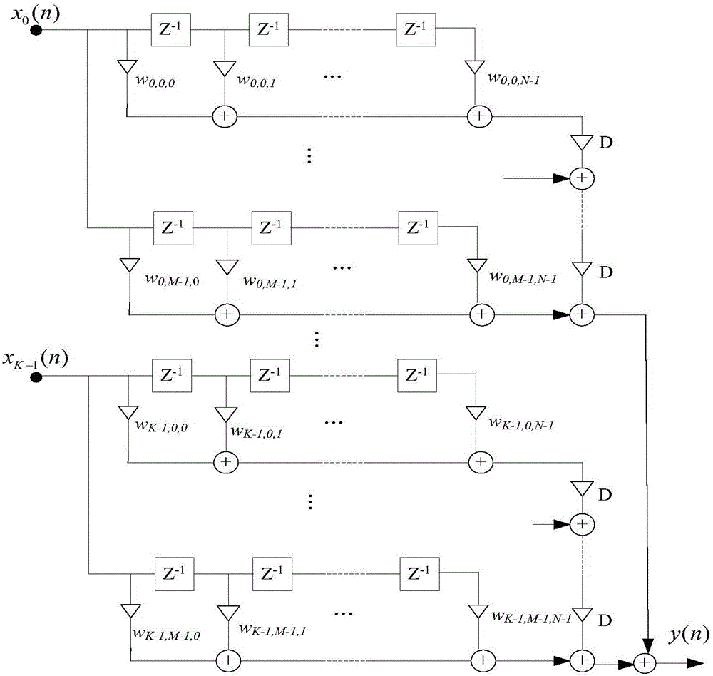
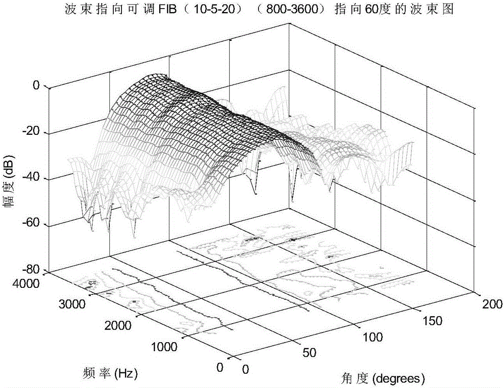
[0147] The existing beamformer design technology includes a broadband robust far-field beamformer algorithm based on convex optimization least squares beam pointing adjustable. The algorithm of the present invention has obvious performance advantages when the frequency band distribution of the processing voice signal is wide . For this reason, an example is given to illustrate the performance comparison of the two algorithms in the same environment. Consider the formation of the Farrow structure beamformer: the number of array elements is 10, the order is 5, the number of taps is 20, the signal frequency band is distributed in [800Hz, 3600Hz], the array element spacing is 5cm, and the adjustable direction range is from 40° to 140°, the reference frequency is 8000Hz, a...

Embodiment 2

[0149] The method of the invention shows that the Farrow structure beamformer itself has systematic errors. Calibration work plays a large role in this invention. The root cause of this step is that the Farrow structure beamformer itself has systematic errors. We demonstrate this theory with concrete examples.

[0150] Assume that there is a uniformly distributed line of microphones with a dimension of 10×5×20, that is, there are 10 microphones, and each microphone is connected to a 5th-order FIR filter, and each FIR has 20 taps. The distance between adjacent microphones is 5cm, and the sampling frequency is f s = 8000Hz. The beam adjustable direction range Ψ is set to The frequency range of interest Ω is [1000-3000]Hz, the reference frequency f r =2600. In each beam pointing, the passband bandwidth (PW) is set to 40°. Within the range of angles we define, each beam points down to the left and right stop bands [0°, φ d -PW / 2-20°], [φ d +PW / 2+20°,180°], where φ d is ...

Embodiment 3

[0153] The method of the present invention accounts for the effect of calibration work on the performance of the Farrow-SRP-PHAT algorithm. The calibration work was done to remove systematic errors of the Farrow structure beamformer. This step plays a large role in the method of the present invention.

[0154] The speaker is located at coordinates (2.6, 2.8) m, and the center point of the microphone array is located at (3, 0) m;

[0155] Considering that the adjustable beam direction ranges from 40° to 140° with an interval of 2°, 10 Monte Carlo experiments are performed. Calculate the mean and variance of these 10 results, and use the root mean square error as the evaluation index.

[0156] Figure 9 It is the performance comparison diagram of the simulation in the reverberation noise environment with the signal-to-noise ratio of 10dB and 5dB, the reverberation of 300ms to 800ms and the interval of 50ms; Figure 10 It is the performance comparison chart of the simulation ...


PUM


Abstract

The invention discloses a fast SRP sound source positioning method. The method comprises the steps that the optimal weight of a Farrow structure beamformer is acquired; the phase weighting function of the Farrow structure beamformer SRP-PHAT is calculated; the sum of generalized cross-correlation functions of all pairwise microphones of the Farrow structure beamformer SRP-PHAT is calculated and latched; product adding is carried out on a latched output signal and a unique yawing parameter D relevant to the scanning angle of the Farrow structure beamformer, so as to acquire the instantaneous power of a corresponding scanning point; the maximum peak is searched to acquire a corresponding positioning angle theta r'; and finally calibration is carried out to eliminate system errors of the Farrow structure beamformer to acquire a final theta r. Compared with former SRP-PHAT, the method provided by the invention has the advantages of reduced computation amount, higher reverberation and noise robustness, and higher azimuth estimation accuracy.

Description

technical field [0001] The invention relates to a sound source localization technology, in particular to a method for SRP sound source localization. Background technique [0002] Sound source localization techniques are mainly divided into three categories, namely beamforming methods based on maximum controllable response power, methods using high-resolution spectrum estimation, and two-step localization methods based on time delay estimation. In 2002, J.H.DiBiase (see literature [1] J.H.DiBiase. A high-accuracy, low-latency technique for talker localization in reverberant environments [D]. Providence RI, USA: Brown University, 2000 and literature [2] Tan Ying, Yin Fuliang, Li Xilin. Improved SRP-PHAT sound Source localization method [J]. Journal of Electronics and Information Technology, 2006, 28 (7): 1223-1227. See literature [3] JacekP.Dmochowski.AGeneralizedSteeredResponsePowerMethodforComputationallyViableSourceLocalization.IEEEtransactionsonaudio,speech,andlanguageproc...

Claims


Application Information

Patent Timeline
IPC IPC(8): G01S5/22
CPCG01S5/22
Inventor 尹明婕陈华伟
Owner NANJING UNIV OF AERONAUTICS & ASTRONAUTICS
Why Eureka
Try Eureka