
Multi-input multi-output UHF RFID tag antenna

An RFID tag, multi-output technology, applied in the field of radio frequency identification, to achieve the effect of reducing the size of the antenna, increasing the working frequency band, and improving the impedance coupling characteristics

Inactive Publication Date: 2015-11-11
INST OF ELECTRONICS & INFORMATION ENG IN
View PDF5 Cites 2 Cited by
  • Summary
  • Abstract
  • Description
  • Claims
  • Application Information

AI Technical Summary

Problems solved by technology

[0005] Generally speaking, the tag antennas of passive UHF RFID systems are single antennas, that is, single-input and single-output antennas. The channel capacity and anti-interference performance of such antennas cannot be compared with those of multiple-input and multiple-output antennas.

Method used


Image

  • Multi-input multi-output UHF RFID tag antenna
  • Multi-input multi-output UHF RFID tag antenna

Examples


Embodiment Construction

[0031] The principles and features of the present invention are described below in conjunction with the accompanying drawings, and the examples given are only used to explain the present invention, and are not intended to limit the scope of the present invention.

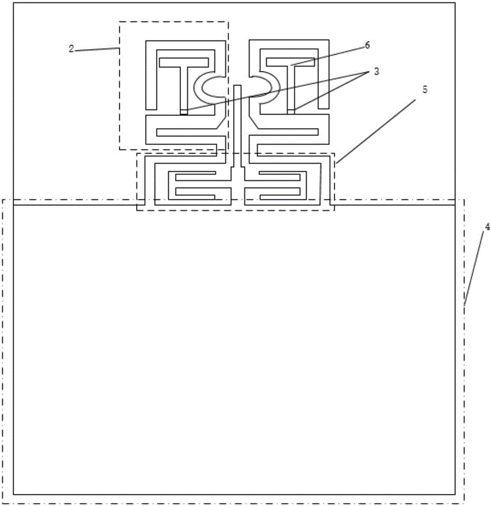
[0032] Such as figure 1 and figure 2 As shown, a multi-input and multi-output UHF RFID tag antenna of the present invention includes an insulating substrate 1, and the insulating substrate 1 is used as a bottom plate, and a microstrip antenna radiation part is provided;

[0033] Wherein, take the whole microstrip antenna radiation part high 14.85mm, width 14mm as an example; the microstrip antenna radiation part includes filter 5, a pair of single antenna 2 and microstrip line 6; Above, each single antenna 2 is respectively connected to the microstrip line 6 through the feed port 3, and the single antenna 2 is wound around the microstrip line 6;

[0034] A pair of single antenna 2, used to receive the electrical ...


PUM


Abstract

The present invention relates to a multi-input multi-output UHF RFID tag antenna which comprises an insulation substrate which is used as a bottom plate and is provided with a microstrip antenna radiating part. The microstrip antenna radiating portion comprises a filter, a pair of single antennas and a microstrip line. The pair of single antennas is symmetrically arranged on the filter. Each of the single antennas is connected to the microstrip line through a feed port respectively and is wound around the microstrip line. The pair of single antennas is used for receiving an electric signal transmitted by a reader and transmitting the electric signal to the filter. The filter is used for filtering the signal noise of the electric signal transmitted by the single antenna and obtaining the electric signal of a needed frequency, and thus transmitting the electric signal to the microstrip line through the single antennas via the feed port. The microstrip line is used as a feed source and transmitting the electric signal of a needed frequency to the processing chip in a tag via the feed port. The multi-input multi-output UHF RFID tag antenna has the advantages of simple structure and small size and has a plurality of operating frequency bands.

Description

technical field [0001] The invention relates to the technical field of radio frequency identification, in particular to a multi-input multi-output ultra-high frequency RFID tag antenna. Background technique [0002] Radio Frequency Identification (RFID) technology, also known as radio frequency identification, is a communication technology that can identify specific targets through radio signals and read and write related data without the need for mechanical or optical contact between the identification system and specific targets. As a key technology for building the Internet of Things, RFID technology has attracted people's attention in recent years. In the application of the Internet of Things, the radio frequency identification system includes a reader, which completes automatic identification through wireless communication between the antenna and the electronic tag. [0003] However, the traditional antennas used in RFID systems, whether they are dipole antennas or heli...

Claims


Application Information

Patent Timeline
Patent Type & Authority Applications(China)
IPC IPC(8): H01Q1/38H01Q1/50H01Q5/364H01Q21/00
Inventor 向勇苏阳蒋常龙王维
Owner INST OF ELECTRONICS & INFORMATION ENG IN
Learn More