Integrated Scan Head for Optical, Ultrasound, Photoacoustic Multimodal Microscopy

A technology of microscopic imaging and scanning head, which is applied in ultrasonic/acoustic/infrasonic diagnosis, application, medical science, etc. It can solve the problems of cumbersome replacement, low degree of integration, and inconvenient operation, so as to improve detection accuracy and integration High degree, not easily deformed effect

Active Publication Date: 2017-12-08
SOUTH CHINA NORMAL UNIVERSITY
View PDF9 Cites 0 Cited by
  • Summary
  • Abstract
  • Description
  • Claims
  • Application Information

AI Technical Summary

Problems solved by technology

However, there are still some deficiencies in the above patents: First, there is no imaging navigation and precise positioning of the detection part, so that the position of the scanning head needs to be corrected repeatedly, which is inconvenient to operate, and the three imaging modes of optical, photoacoustic and ultrasonic cannot be realized It is difficult to provide more useful information; second, the scanning galvanometer structure is used, which cannot realize photoacoustic microscopy imaging in a large field of view; third, the degree of integration is not high, and the disassembly and replacement of devices It is necessary to re-adjust the entire optical path system, and there is no signal amplification circuit system in the scanning head; fourth, the structure of the bowl-shaped hollow ultrasonic detector and the photoacoustic confocal coupler is relatively complicated, and it is inconvenient to operate. The film is easy to be damaged after long-term use, and the replacement is cumbersome, and the specification and model of the coupler are relatively single. It is difficult to replace the model of different couplers for different parts and diseases.

Method used


Image

  • Integrated Scan Head for Optical, Ultrasound, Photoacoustic Multimodal Microscopy
  • Integrated Scan Head for Optical, Ultrasound, Photoacoustic Multimodal Microscopy
  • Integrated Scan Head for Optical, Ultrasound, Photoacoustic Multimodal Microscopy

Examples


Embodiment Construction

[0034] The present invention will be further described in detail in conjunction with the accompanying drawings and specific embodiments.

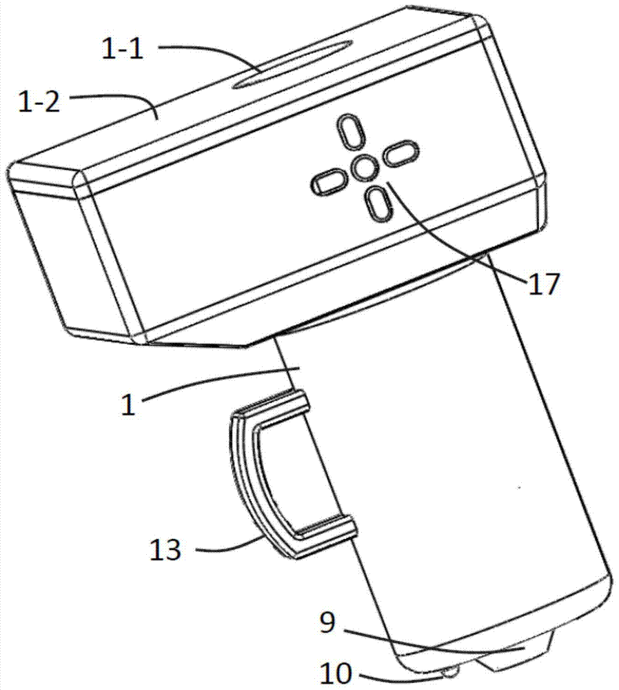
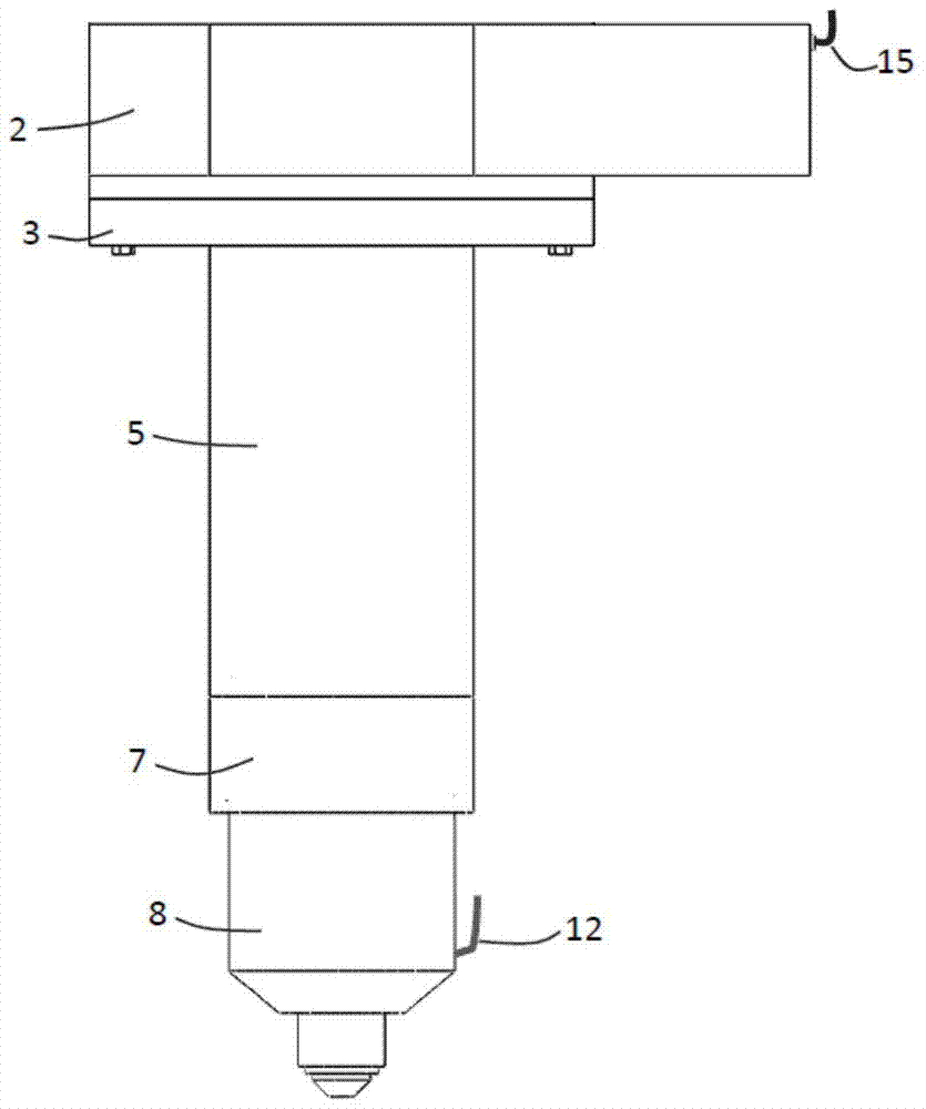
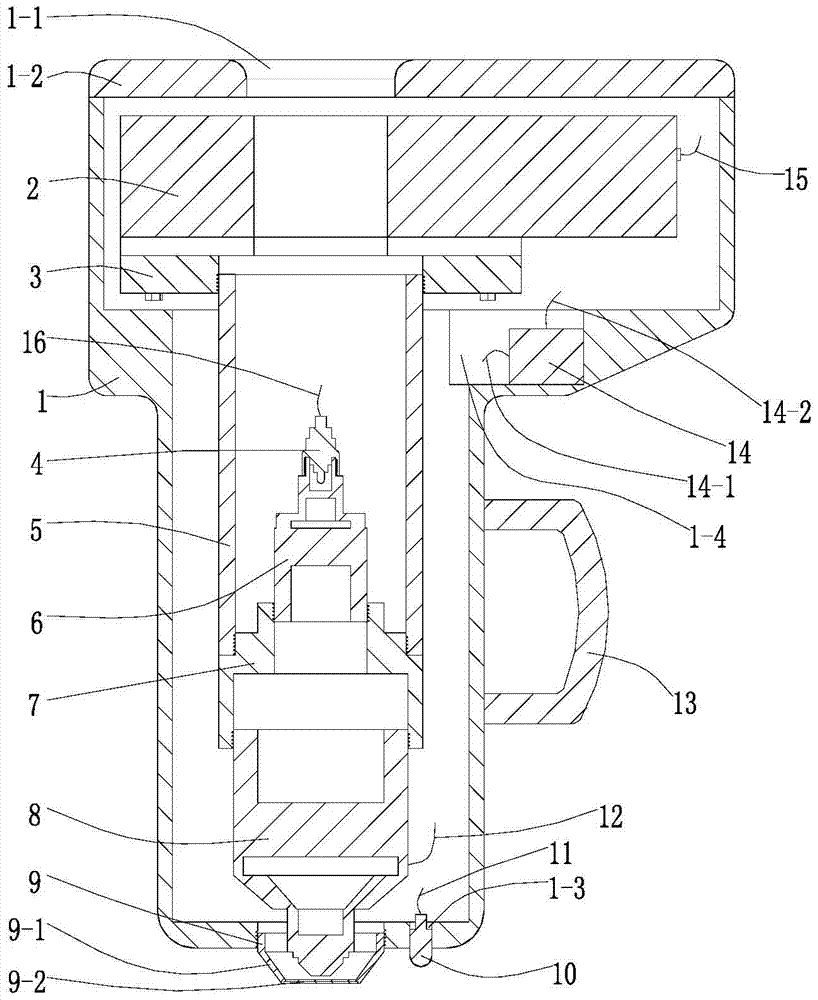
[0035] Such as figure 1The integrated multifunctional scanning head for optical, ultrasonic and photoacoustic multi-mode microscopic imaging shown includes: housing 1, two-dimensional motor scanning platform 2, adapter plate 3, single-mode optical fiber 4, adapter tube 5, optical fiber Coupling collimator 6, threaded tube 7, integrated detector 8, photoacoustic coupler 9, adjustable focus optical camera 10, adjustable focus optical camera power cord 11, integrated detector signal line 12, handle 13, signal Amplifier 14, two-dimensional motor scanning platform power line and control line, single-mode optical fiber input line 16, and control buttons 17.

[0036] The two-dimensional motor scanning platform 2 that drives the adapter plate 3 to move, the adapter plate 3, the adapter pipe 5, the threaded pipe 7, and the integrated detector 8 are...


PUM


Abstract

The invention relates to an integrated scanning head for optical, ultrasonic, and photoacoustic multi-mode microscopic imaging, a two-dimensional motor scanning platform that drives an adapter plate to move, an adapter plate, an adapter tube, a threaded tube, and an integrated detector Fasten and connect sequentially, the single-mode fiber set on the upper end of the fiber-coupled collimator, the fiber-coupled collimator set on the upper end of the threaded tube, and the integrated detector set at the lower end of the threaded tube follow the axial direction of the adapter tube in sequence Coaxial arrangement; the photoacoustic coupler installed at the lower end of the scanning head surrounds the part of the integrated detector exposed at the lower end of the scanning head; the integrated detector is connected to the signal amplifier; the described integrated detector is installed at the lower end of the shell A part of the adjustable focus optical camera is exposed from the casing; the control keys for controlling the movement of the scanning head and data collection are installed on the casing. The invention can obtain multi-parameter physical information and multi-scale structural imaging of detection parts, and belongs to the technical fields of microscopic imaging and non-destructive testing.

Description

technical field [0001] The invention relates to the technical fields of microscopic imaging and non-destructive testing, in particular to an integrated scanning head for optical, ultrasonic and photoacoustic multi-mode microscopic imaging. Background technique [0002] As a new generation of medical imaging method under rapid development, photoacoustic imaging combines the characteristics of optical imaging and ultrasonic imaging, that is, the non-destructive and highly selective excitation characteristics of optical imaging and the low attenuation and high penetration of ultrasonic imaging. sexual characteristics. Photoacoustic imaging technology is based on the photoacoustic effect. When a short-pulse laser irradiates biological tissue, the absorber located in the tissue absorbs the pulsed light energy, thereby heating up and expanding to produce ultrasound, that is, the photoacoustic effect. The photoacoustic imaging method combines the advantages of high contrast of opt...

Claims


Application Information

Patent Timeline
Patent Type & Authority Patents(China)
IPC IPC(8): A61B5/00A61B8/00
Inventor 杨思华马海钢许栋邢达
Owner SOUTH CHINA NORMAL UNIVERSITY
Why Eureka
Try Eureka