
Front and rear end-mounted compaction wheel device for road roller and operation method thereof

An operation method and technology of road rollers, which are applied in the field of construction machinery, can solve problems such as time-consuming and labor-consuming, high cost, and low flatness, and achieve the effects of saving manpower and material costs, avoiding repeated operations, and simple replacement and disassembly

Active Publication Date: 2015-11-18
中交二公局第四工程有限公司
View PDF5 Cites 5 Cited by
  • Summary
  • Abstract
  • Description
  • Claims
  • Application Information

AI Technical Summary

Problems solved by technology

[0007] Existing road rollers are widely used, especially for foundation compaction of roads, railways, dams, airports, buildings, factories, and residences. When there are bumps or pits, the staff in the operating room cannot understand and grasp the smoothness of the road surface, which may leave uneven road sections on the ground, especially after the agglomerated dirt is generated during the road rolling process, the pressure wheel surface The agglomerated dirt on the surface cannot be completely removed, and it is easy to cause agglomeration again, further causing uneven road sections, and such uneven road sections are very important for roads, railways, dams, airports, buildings, factories, residences, etc. It is very deadly and dangerous. Although the existing technology can be processed to a certain extent, it is time-consuming and labor-intensive, and the cost is relatively large.

Method used


Image

  • Front and rear end-mounted compaction wheel device for road roller and operation method thereof
  • Front and rear end-mounted compaction wheel device for road roller and operation method thereof
  • Front and rear end-mounted compaction wheel device for road roller and operation method thereof

Examples


Embodiment 1

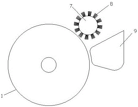
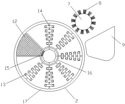
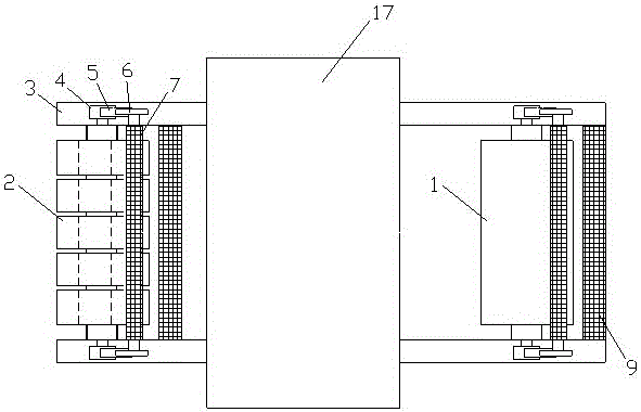
[0036] refer to Figure 1 to Figure 4 As shown, a split arrangement of the pressure roller of a road roller includes a wheel body 1, a wheel body 2 and a car body 18, the wheel body 2 2 is located in front of the car body 18, and the wheel body 1 is located in the car body 18 At the rear, the wheel body one 1 and the wheel body two 2 are all equipped with a pair of pressure wheel frames 3, and the bottom of the pressure wheel frame 3 corresponding to the wheel body one 1 is provided with lifting wheels, and the pressure wheel frame 3 is provided with a first wheel. Gear 4, relay gear 5 and tail gear 6, described head gear 4 is linked with wheel body one 1 or wheel body two 2, and the lifting device in the lifting wheel is an air pump etc., and described tail gear 6 is linked with brush wheel 7, The brush wheel 7 is provided with bristles 8, and there is a recovery box 9 corresponding to the bottom of the brush wheel 7. One side of the pressure wheel frame 3 is provided with tw...


PUM

PropertyMeasurementUnit
Particle sizeaaaaaaaaaa

Abstract

The invention discloses a front and rear end-mounted compaction wheel device for a road roller and an operation method thereof. The device comprises a wheel body I, a wheel body II and a vehicle body, wherein the wheel body II is positioned in the front part of the vehicle body; the wheel body I is positioned in the rear part of the vehicle body; the wheel body I and the wheel body II are respectively provided with a pair of compaction wheel frames; the bottoms of the compaction wheel frames corresponding to the wheel body I are provided with lifting wheels; each of the wheel body I and the wheel body II is made of 25% of gravel, 15% of limestone, 20% of cement, 5% of inorganic cementing material, 0.5% of hydroxypropyl methyl cellulose, 1.5% of ground calcium carbonate, 2% of polyethylene fiber, 1% of rubber powder, 7% of kaolin powder, 3% of water, 10% of aggregate and 10% of asphalt; and the particle size of the gravel is greater than 1.7mm, and the cement is portland-pozzolana cement. The compaction wheel device for the road roller has the advantages that the structure is novel, workers in an operation room can know the flatness condition of the pavement in real time, agglomerated dirt can be avoided, and the flatness is high.

Description

technical field [0001] The invention relates to a construction machine, in particular to a pressure wheel device of a road roller arranged at the front and rear ends and an operation method thereof. Background technique [0002] Road rollers belong to the category of road equipment in construction machinery. They are widely used in the filling and compaction operations of large-scale engineering projects such as high-grade highways, railways, airport runways, dams, and stadiums. They can roll sandy, semi-cohesive and cohesive soils, Subgrade stabilized soil and asphalt concrete pavement layer. [0003] When it comes to road rollers, I have to give a brief introduction to the development of compaction technology. As early as in ancient times, people used the hooves of herds to trample, knead and tamp the soil to deal with the foundation of houses and compact dams. And river embankments, before the middle of the 19th century, Western road engineering was mainly paved with gra...

Claims


Application Information

Patent Timeline
IPC IPC(8): E01C19/23E01C19/26
Inventor 梁国锋
Owner 中交二公局第四工程有限公司
Learn More