
Floating semi-active swing hydrofoil tidal current energy catching device

A semi-active, floating technology, used in ocean power generation, engine components, machines/engines, etc., to achieve flexible transmission, easy shallow water application, and low noise

Inactive Publication Date: 2015-11-18
HARBIN ENG UNIV
View PDF9 Cites 11 Cited by
  • Summary
  • Abstract
  • Description
  • Claims
  • Application Information

AI Technical Summary

Problems solved by technology

There are no related invention patents in China about the floating semi-active control of the angle of attack of the hydrofoil to realize the periodic cycle of the hydrofoil.

Method used


Image

  • Floating semi-active swing hydrofoil tidal current energy catching device
  • Floating semi-active swing hydrofoil tidal current energy catching device
  • Floating semi-active swing hydrofoil tidal current energy catching device

Examples


Embodiment Construction

[0017] The present invention will be further described in detail below in conjunction with the accompanying drawings and specific embodiments.

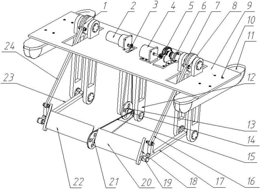
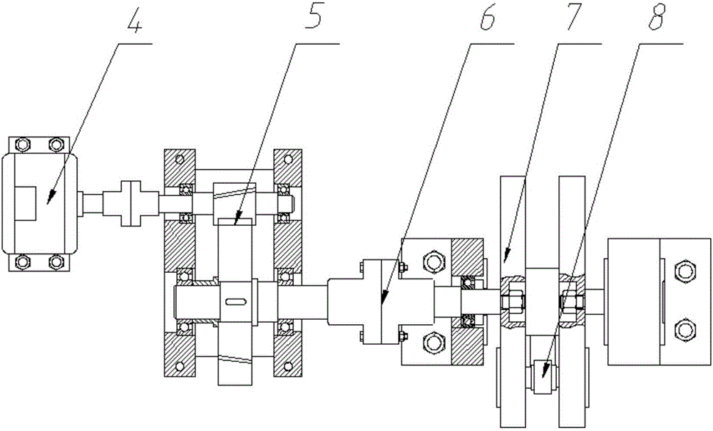
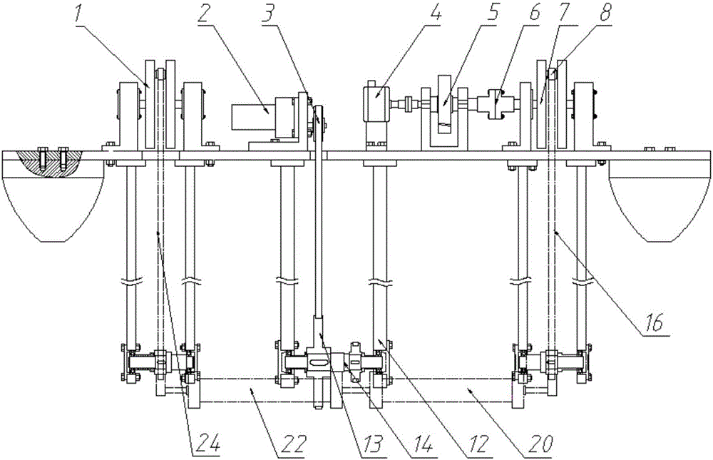
[0018] combine Figure 1 to Figure 6 , The components included in the present invention are: flywheel 1, control motor 2, primary synchronous belt drive 3, generator 4, speed-increasing mechanism 5, elastic coupling 6, flywheel 7, pin shaft 8, flat plate 9, connecting bolt 10 , buoy 11, support plate 12, pulley 13, intermediate shaft 14, secondary synchronous belt drive 15, heave connecting rod 16, heave swing bar 17, airfoil terminal plate 18, airfoil shaft 19, right wing 20, Minor shaft 21, left wing 22, heave swing bar 23, heave connecting rod 24.

[0019] The present invention describes a new type of floating semi-active swing hydrofoil current energy harvesting device, the overall structure is as follows figure 1 , image 3 , Figure 4 and Figure 5 As shown, it mainly includes the energy extraction part of the device, the h...


PUM


Abstract

The invention provides a floating semi-active swing hydrofoil tidal current energy catching device; and the device consists of two sets of crank and rocker mechanisms, wings, synchronous belts and belt wheels, a control motor, an acceleration mechanism, flywheels, floating cylinders, flat plates, a generator and corresponding transmission parts. The vertical swing motion of hydrofoils is converted to the one-way rotation motion of cranks through the transmission of the crank and rocker mechanisms; and after the acceleration mechanism speeds up, the energy is finally transferred to the generator to realize the energy conversion. The motor is used for realizing the real-time control of wing swing angle motion rules; the rotation inertia of the flywheels is used for overcoming the dead point problem in the motion of the crank and rocker mechanisms; and the acceleration mechanism is used for raising the rotation speed into a rated rotation speed range of the generator. The device realizes the energy conversion by using the motion characteristics of the crank and rocker mechanisms, and actively controls the hydrofoil attach angles by using the motor. The device has such advantages as simple structure, convenience for installation, low noise and easy application in shallow water.

Description

technical field [0001] The invention relates to an energy harvesting device, in particular to a floating semi-active swing hydrofoil tidal current energy harvesting device. Background technique [0002] With the excessive consumption of fossil fuels such as oil and coal, the development and utilization of renewable energy such as tidal current energy, wind energy, and solar energy have attracted more and more attention from all over the world. As an important form of ocean energy, tidal current energy, compared with solar energy and wind energy, has the advantages of high energy density, less environmental pollution, regular changes, and good predictability. It is also known as one of the world's top ten clean energy sources in the future. At present, the utilization of tidal current energy is mostly in the form of turbines with rotating blades and corresponding generators for energy capture. However, there are some problems in this tidal current energy capture method, such ...

Claims


Application Information

Patent Timeline
Patent Type & Authority Applications(China)
IPC IPC(8): F03B13/14F03B13/26
CPCY02E10/30
Inventor 徐建安孙洪雨穆永涛宁献良孔德慧李建正徐佳高新
Owner HARBIN ENG UNIV
Learn More