Automatic frequency adjustment fan and control method thereof

A technology of automatic frequency regulation and control method, which is applied in the field of electric fans and can solve the problems such as the inability of automatic adjustment of fans and poor comfort.

Active Publication Date: 2015-11-18
上海爱朴环保科技有限公司
View PDF8 Cites 12 Cited by
  • Summary
  • Abstract
  • Description
  • Claims
  • Application Information

AI Technical Summary

Problems solved by technology

When sleeping and using during the day and night, the human body is in different active states, the fan cannot automatical

Method used


Image

  • Automatic frequency adjustment fan and control method thereof
  • Automatic frequency adjustment fan and control method thereof
  • Automatic frequency adjustment fan and control method thereof

Examples


no. 1 example

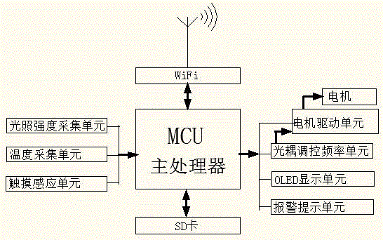
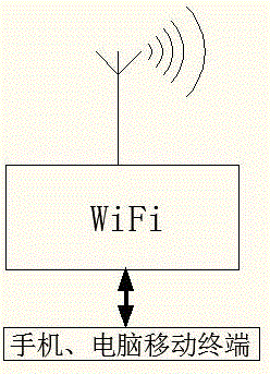
[0033] see figure 1 — Image 6 , the electric fan, its circuit features: including light intensity acquisition circuit unit, temperature acquisition circuit unit, optocoupler control frequency circuit unit, motor drive circuit unit, touch sensing circuit unit, WiFi and Bluetooth communication circuit unit, OLED display circuit unit, Memory expansion circuit unit, alarm prompt circuit unit, power supply circuit, electric fan.

[0034] The light intensity acquisition circuit unit includes a photoresistor RL and a resistor RC, the photoresistor RL and the resistor RC are connected in series between VCC and GND, and one end of the nodes of RL and RC is connected to the IO port of the microcontroller.

[0035] The illumination intensity acquisition circuit unit is connected with an illumination intensity sensor to the single-chip microcomputer, and can obtain indoor illumination intensity information by collecting and processing the AD value of the photoresistor.

[0036] The abo...

no. 2 example

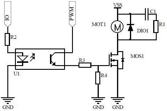
[0043] see image 3: The optocoupler control frequency circuit unit includes optocoupler U1 and resistor R2. The negative pole of the transmitter tube of optocoupler U1 is grounded, the positive pole is connected to resistor R2, the other end of resistor R2 is connected to the IO port of the microcontroller, and the collector of optocoupler U1 is connected to the IO port of the microcontroller. The port is connected, and the emitter is connected to the motor drive input.

[0044] see image 3 : The motor drive circuit unit includes N-type MOS tube MOS1, resistors R1, R3, R4, diode DIO1, capacitor C1, one end of resistor R3 is connected to the emitter of the optocoupler, and one end is connected to the gate of the N-type MOS tube.

[0045] In the motor drive circuit unit, when the single-chip microcomputer generates a frequency with a certain duty ratio to the collector of the optocoupler U1, the emitting tube of the optocoupler U1 emits light, then the collector and the emitt...

no. 3 example

[0050] like Figure 4 It is the PWM output curve corresponding to different temperatures in the daytime and nighttime conditions.


PUM


Abstract

Provided are an automatic frequency adjustment fan and a control method thereof. A single chip microcomputer acquires and processes indoor temperature and illumination intensity and outputs the frequencies of duty ratios corresponding to the indoor temperature and the illumination intensity acquired at the moment to a collector electrode of an optical coupler by utilizing a PWM output function inside the single chip microcomputer, and one end of the collector electrode of the optical coupler is connected with a driving signal input end of a motor so as to achieve motor speed control. One lead pin of the single chip microcomputer is connected with a transmitting tube of the optical coupler, high and low levels corresponding to the indoor temperature and the illumination intensity acquired at the moment, the delay time of the high level and the delay time of the low level are output through the pin, and further adjustment and control of the stalling frequency of the motor are achieved. A user can set various parameters through client-side software of a mobile phone and a computer and design a sleep curve suitable for himself/herself, can upload the sleep curve designed by himself/herself to a client platform through cloud services and can download sleep curves shared by others through the client platform as well.

Description

technical field [0001] The invention relates to an electric fan, in particular to an automatic frequency-regulating fan and a control method thereof. Background technique [0002] In the industry, the adjustment of the speed of electric fans is achieved by manual touch switches or key switches. For example, the patent application number is 201110442743.0, which discloses a DC brushless electric fan and its control method: the user generates an action signal by adjusting the encoder knob, and the single-chip computer analyzes and processes the knob signal after receiving the signal and outputs a certain duty cycle constant frequency to DC brushless motors. The user needs to manually adjust the encoder to adjust the fan speed, which is troublesome to adjust. The adjusted motor speed and stop frequency cannot change with the temperature and light intensity of the surrounding environment. For example, when using in summer, the user initially sets a comfortable wind speed. When...

Claims


Application Information

Patent Timeline
IPC IPC(8): F04D27/00
Inventor 宋彦震
Owner 上海爱朴环保科技有限公司
Why Eureka
Try Eureka