
Novel large user capacity optical code division multiple access codec

An optical code division multiple access and decoder technology, which is applied in the fields of information technology and optical fiber communication, can solve the problems of narrow reflection peak, multiple access interference of user spread spectrum sequence, high precision requirements, etc., and achieve the effect of improving performance and preventing crosstalk

Inactive Publication Date: 2015-11-18
TIANJIN UNIV
View PDF9 Cites 8 Cited by
  • Summary
  • Abstract
  • Description
  • Claims
  • Application Information

AI Technical Summary

Problems solved by technology

[0009] Although the above-mentioned patents realize the encoding and decoding of the OCDMA system, they have some defects. For example, the OCDMA system using the fiber grating as the encoder requires that the fiber gratings that form the array be matched consistently during production, and the accuracy requirements are very high, and the grating is used during use. Instability, the reflection peak is not narrow enough, and there is inevitably multiple access interference between user spread spectrum sequences, which limits the number of users; the micro-ring resonant cavity designed using the principle of micro-nano photonics is an OCDMA system for codecs, It has the characteristics of low loss and programmable, but the existing scheme only applies to one-dimensional encoding and decoding, which limits the expansion of the number of system users

Method used


Image

  • Novel large user capacity optical code division multiple access codec
  • Novel large user capacity optical code division multiple access codec

Examples


Embodiment Construction

[0019]Specific embodiments of the present invention will be described in detail below in conjunction with the accompanying drawings. If there are exemplary contents in these embodiments, they should not be construed as limiting the present invention.

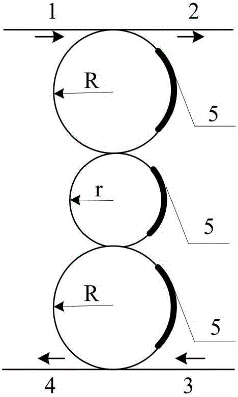
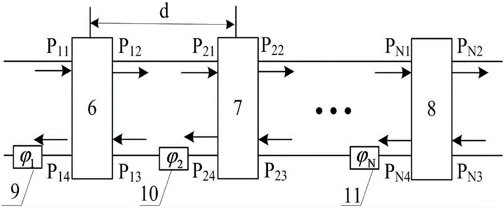
[0020] The codec involved in the present invention is composed of a coupled series waist drum microring array based on the vernier effect. Here, the waist-drum three-ring structure in series is chosen to illustrate the encoding and decoding principle of the present invention.

[0021] For the unequal large three-ring coupling structure, there are many ways to connect it in series. The present invention selects the coupling series connection with the best coding and decoding effect on the basis of the 3dB bandwidth of the reflection spectrum of the series microring, the rectangularity factor and the pseudo-mode suppression characteristics. Big ring-small ring-big ring drum type three-ring structure, such as figure 1 shown. Wher...


PUM


Abstract

The invention discloses a novel large user capacity optical code division multiple access codec. After a light signal composed of a number of wavelengths is input from the input port of a waveguide, wavelengths which meet the resonance condition of each micro-ring at the same time pass micro-rings which are connected in series and are output from the downloaded end of another waveguide, and other wavelengths which do not meet the condition are passed away from the transfer port of the waveguide. A thermal resistance device on each micro-ring is adjusted to control the wavelength change of an annular resonator, so as to realize wavelength selection. A phase shifter on a bus is controlled to adjust the phase corresponding to the reflection wave of each group of micro-ring, so as to complete the specific phase change of different wavelengths. Wavelength-phase two-dimensional coding is realized. In a similar fashion, each wavelength light signal is successively reflected in the same manner. The phase is respectively modulated. Coding through light signals is realized. A decoder is in the reverse arrangement structure of a coder. According to the invention, the user capacity of an optical code division multiple access system is expanded; the performance of the codec is improved; and as the number of the columns of the micro-rings which are connected in series increases, the user capacity is in e exponential growth.

Description

technical field [0001] The invention belongs to the technical fields of information technology and optical fiber communication, and relates to a large user capacity optical code division multiple access codec based on a microring resonant cavity. Background technique [0002] The optical code division multiple access (OCDMA) system combines the advantages of code division multiple access technology and optical fiber communication, and uses the optical encoder / decoder as a high-speed optical signal processor, which has the advantages of simple access mode, large system capacity, and low access delay , flexible address allocation, fully asynchronous transmission, high quality of service control and high information security, etc., is one of the most promising solutions for future high-speed optical fiber LAN and user access network. As one of the key technologies and core components of the OCDMA system, the structure and characteristics of the codec directly affect the power c...

Claims


Application Information

Patent Timeline
IPC IPC(8): H04J14/00H04B10/516H04B10/548H04B10/60
Inventor 贾大功杜闯张红霞刘铁根张以谟
Owner TIANJIN UNIV
Learn More