Annular magnetic core using Fe iron-based nanocrystalline soft-magnetic alloy and magnetic component using said annular magnetic core

A technology of soft magnetic alloys and nanocrystals, applied in magnetic cores/yokes, magnetic materials, magnetic objects, etc., can solve problems such as difficulty in maintaining high AC relative permeability, achieve excellent pulse attenuation characteristics, and reduce processing hours , Reduce the effect of excellent performance

Active Publication Date: 2015-11-18
HITACHI METALS LTD
View PDF9 Cites 10 Cited by
  • Summary
  • Abstract
  • Description
  • Claims
  • Application Information

AI Technical Summary

Problems solved by technology

However, it is known that the magnetic core with the composition specifically described in JP 2006-525655 has the disadvantage that it is difficult to maintain a high AC relative magnetic permeability μr (ACspecificpermeability) if the DC applied magnetic field strength is 150A / m or more.

Method used


Image

  • Annular magnetic core using Fe iron-based nanocrystalline soft-magnetic alloy and magnetic component using said annular magnetic core
  • Annular magnetic core using Fe iron-based nanocrystalline soft-magnetic alloy and magnetic component using said annular magnetic core
  • Annular magnetic core using Fe iron-based nanocrystalline soft-magnetic alloy and magnetic component using said annular magnetic core

Examples


Embodiment 1

[0081] By single roll method, will have Fe 70.7 Ni 5.0 Cu 0.8 Nb 2.8 Si 10.9 B 9.8 (atomic %) melts were sprayed onto the surface of a high-speed rotating copper roll through nozzles and quenched to obtain alloy strips with thicknesses of 16 μm, 18 μm and 23 μm and widths of 53 mm. It was confirmed by X-ray diffraction measurement that the structures of these alloy ribbons were substantially amorphous. The crystallization temperature Tx of this alloy obtained by differential scanning calorimetry was 490°C.

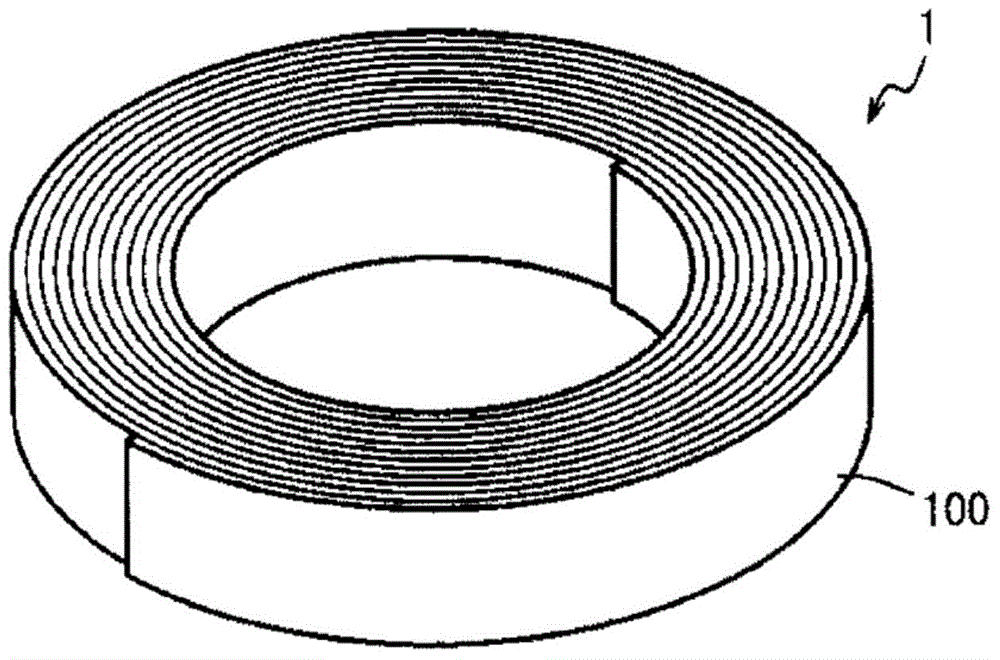
[0082] Each ribbon was cut to obtain two ribbons with a width of 25 mm. Each thin ribbon was wound to obtain an annular tape-wound magnetic core (space factor: 0.9) having an outer diameter of 24.5 mm, an inner diameter of 21 mm, and a height / width of 25 mm. Put the ring-shaped tape-wound magnetic core in the heat treatment furnace controlled by nitrogen atmosphere, and carry out the following heat treatment. The temperature is raised from 420°C to the highest tempe...

Embodiment 2

[0101] Use the thin strip (thickness 18 μm) produced in Example 1 to make a ring-shaped tape-wound magnetic core with an outer diameter of 36.0 mm, an inner diameter of 17.5 mm, and a height / width of 25 mm, put it into a casing, and wind an enameled wire with a wire diameter of 2.5 mm. 17 turns to make a choke coil. The impedance of the choke coil is shown in Figure 5 middle. Depend on Figure 5 It can be seen that the choke coil of Example 2 exhibits excellent impedance performance from a low frequency range to a high frequency range.

[0102] The direct current superposition inductance characteristics of the choke coil of Example 2 and the choke coil of Comparative Example 1 were evaluated. show the result in Image 6 . Depend on Image 6 It can be seen that the choke coil of Example 2 is superior to the choke coil of Comparative Example 1 in the direct current superimposed inductance characteristic.

Embodiment 3

[0104]Using the thin ribbon (thickness 18 μm) produced in Example 1 to fabricate an annular tape-wound magnetic core with an outer diameter of 17.8 mm, an inner diameter of 13.8 mm, and a height / width of 25 mm, thereby producing Figure 7 The three-phase common mode choke coil shown. The annular magnetic core is housed in an insulating case 6, and a partition plate 8 for dividing the winding area is provided in the center of the case. The coils 7a, 7b, and 7c of the respective phases are formed by winding an enameled wire with a wire diameter of 2.5 mm three turns. The frequency characteristics of the impedance and inductance of the three-phase common mode choke coil are shown in Figure 8 . In the figure, the solid line represents inductance, and the dotted line represents impedance. Depend on Figure 8 It can be seen that the three-phase common mode choke coil of Example 3 exhibits excellent impedance performance in the low frequency range to the high frequency range.


PUM

PropertyMeasurementUnit
thicknessaaaaaaaaaa
thicknessaaaaaaaaaa
particle sizeaaaaaaaaaa

Abstract

An annular magnetic core that comprises an iron-based nanocrystalline soft-magnetic alloy, some of the iron in which is substituted with nickel and/or cobalt. Said annular magnetic core exhibits a relative AC permeability (μr100k(50)) of at least 4,000 at a frequency of 100 kHz in a 50 A/m applied DC magnetic field, a relative AC permeability (μr100k(150)) of at least 2,500 at a frequency of 100 kHz in a 150 A/m applied DC magnetic field, a maximum permeability (μMax) of at most 8,000 in a 400 A/m applied DC magnetic field, and a magnetic flux density (B400) of at least 1.3 T.

Description

technical field [0001] The present invention relates to a ring core used in a noise filter disposed between a power supply and an electronic device to suppress noise at a large current, and a magnetic component using the same. Background technique [0002] Such as Figure 9 As shown, in an electronic circuit including a power supply 201, an inverter (inverter) 202, and an electronic device 203, etc., there are high-frequency switching noises generated by the conversion part on the power supply 201 side, and high voltage generated by the electronic device 203 such as a motor. Noise such as pulsating noise can cause malfunctions. In order to prevent such noise, a noise filter 10 is inserted between the power supply 201 , the inverter 202 , and the electronic device 203 . [0003] Figure 10 The general structure of the noise filter 10 for three-phase power supply is shown. In this noise filter 10, between the input terminal 101a on the power supply side and the output termi...

Claims


Application Information

Patent Timeline
Patent Type & Authority Applications(China)
IPC IPC(8): H01F27/25C22C38/00C22C45/02H01F1/14H01F3/04
CPCC22C38/00C22C45/02H01F1/15333H01F3/04C21D1/74C21D1/78C21D9/0068C22C38/002C22C38/02C22C38/08C22C38/12C22C38/16C22C38/32
Inventor 直江昌武滨口康博萩原和弘
Owner HITACHI METALS LTD
Why Eureka
Try Eureka