
Cold-rolled strip vacuum cleaning system and its control method

A technology for vacuum cleaning and cold-rolled strip, applied in metal rolling, metal rolling, manufacturing tools, etc., can solve the problems of inability to ensure complete removal of water on the surface of strip, complicated equipment, consumption of large steam medium and electric energy, etc. Achieving good treatment effect, reducing production cost and reducing labor intensity of workers

Active Publication Date: 2017-03-22
WISDRI ENG & RES INC LTD
View PDF7 Cites 0 Cited by
  • Summary
  • Abstract
  • Description
  • Claims
  • Application Information

AI Technical Summary

Problems solved by technology

[0004] However, even through the simultaneous drying operation of double squeeze rollers or three squeeze rollers, the complete removal of moisture on the surface of the strip cannot be guaranteed. Usually, a strip dryer needs to be installed after the squeeze rollers. By blowing cold air (using The high-pressure blower directly blows the cold air to the strip steel to take away the moisture on the strip surface) and the hot air blowing method (the high-pressure blower blows the hot air heated by the steam heat exchanger to above 100 ℃ to the strip surface to take away the strip steel surface moisture) to further dry the strip
The strip dryer needs to be equipped with high-power high-pressure fans, heat exchangers, steam flow regulating valves, air flow regulating valves, air temperature and steam temperature detection devices. The equipment is relatively complicated and consumes a lot of steam medium and electric energy.

Method used


Image

  • Cold-rolled strip vacuum cleaning system and its control method
  • Cold-rolled strip vacuum cleaning system and its control method
  • Cold-rolled strip vacuum cleaning system and its control method

Examples


Embodiment Construction

[0041] It should be understood that the specific embodiments described here are only used to explain the present invention, not to limit the present invention.

[0042] It should be noted that, in the description of the present invention, the terms "horizontal", "vertical", "upper", "lower", "front", "rear", "left", "right", "vertical", The orientation or positional relationship indicated by "horizontal", "top", "bottom", "inner", "outer", etc. is based on the orientation or positional relationship shown in the drawings, and is only for the convenience of describing the present invention and simplifying the description, and It is not to indicate or imply that the device or element referred to must have a particular orientation, be constructed in a particular orientation, or operate in a particular orientation, and thus should not be construed as limiting the invention. In addition, the terms "first", "second", etc. are used for descriptive purposes only, and should not be cons...


PUM


Abstract

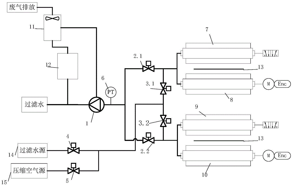
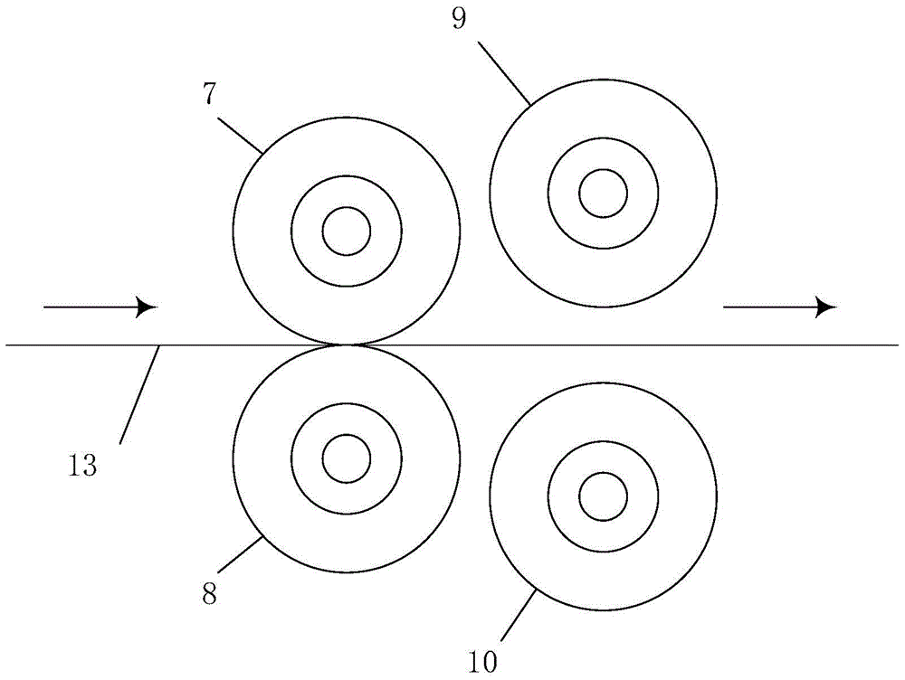
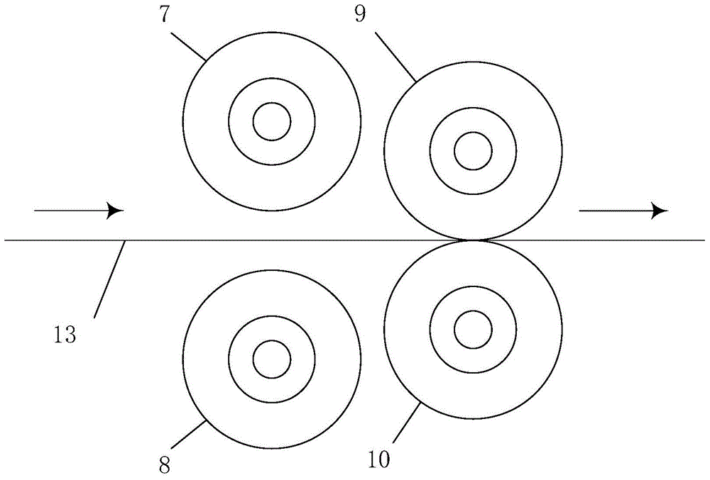
The invention discloses a vacuum cleaning system for cold-rolling strip steel. The vacuum cleaning system comprises a vacuum pump, a first vacuum roller, a second vacuum roller, a first vacuum roller suction stop valve, a second vacuum roller suction stop valve, a first vacuum roller back-washing stop valve, a second vacuum roller back-washing stop valve, a back-washing filtered water stop valve and a converse-blowing compressed air stop valve. The first vacuum roller suction stop valve is located on a pipeline between the first vacuum roller and the vacuum pump. The second vacuum roller suction stop valve is located on a pipeline between the second vacuum roller and the vacuum pump. The back-washing filtered water stop valve is located on a pipeline between a filtered water source and the first vacuum roller. The converse-blowing compressed air stop valve is located on a pipeline between a compressed air source and the first vacuum roller. The first vacuum roller back-washing stop valve is installed on a pipeline between the back-washing filtered water stop valve and the first vacuum roller. The vacuum cleaning system for the cold-rolling strip steel can conduct cleaning and dehumidifying treatment on the surface of the strip steel continuously, and meanwhile the roller replacing frequency is reduced.

Description

technical field [0001] The invention relates to the technical field of steel rolling in the metallurgical industry, in particular to a vacuum cleaning system for cold-rolled strip steel and a control method thereof. Background technique [0002] In the cold rolling treatment line of the metallurgical industry, the squeeze dry is usually set after the process section where the liquid medium participates in the treatment (such as after the acid tank and the cleaning section of the pickling treatment line, after the cleaning section and after the water quenching section of the continuous annealing line). The roller is used to remove the liquid film on the surface of the strip, so as to prevent the liquid (such as acid and rinse water) from the previous process section from being brought into the next process section, which will affect the quality of the strip surface treatment. [0003] The squeeze roller is closely attached to the strip steel through the upper and lower roller...

Claims


Application Information

Patent Timeline
Patent Type & Authority Patents(China)
IPC IPC(8): B21B45/02
Inventor 周登科彭起
Owner WISDRI ENG & RES INC LTD
Learn More