
Smelting furnace for continuously smelting blister copper through copper sulfide concentrate and smelting method of smelting furnace

A copper sulfide and smelting furnace technology, applied in electric furnaces, crucible furnaces, rotary drum furnaces, etc., can solve the problems of potential safety hazards, difficult continuous process, large environmental pollution, etc., and achieve small fluctuations in SO2 concentration, obvious energy-saving effect, and environmental protection. good condition

Active Publication Date: 2015-11-25
YUNNAN TIN
View PDF2 Cites 12 Cited by
  • Summary
  • Abstract
  • Description
  • Claims
  • Application Information

AI Technical Summary

Problems solved by technology

The disadvantage of this method is that the correlation between the three furnaces is too high, and the mutual constraints are relatively large. A little careless operation will make the process difficult to continue. Therefore, this process is rarely popularized and applied at present.
[0004] The above-mentioned equipment and methods are not only complicated in equipment, large in investment, and complicated in process, but also have a common problem, that is, the slag process of smelting copper sulfide concentrate into matte and low copper is not continuous with the process of blowing matte into blister copper. , A converter is required between the two processes, that is, the matte and low-copper slag and mixed melt obtained from the smelting of the previous process are transferred to the blowing furnace for blowing blister copper through intermediate equipment, which consumes energy, time, and low work efficiency. The overflow of flue gas in the converter process will cause great environmental pollution, and there are still potential safety hazards

Method used


Image

  • Smelting furnace for continuously smelting blister copper through copper sulfide concentrate and smelting method of smelting furnace

Examples


Embodiment Construction

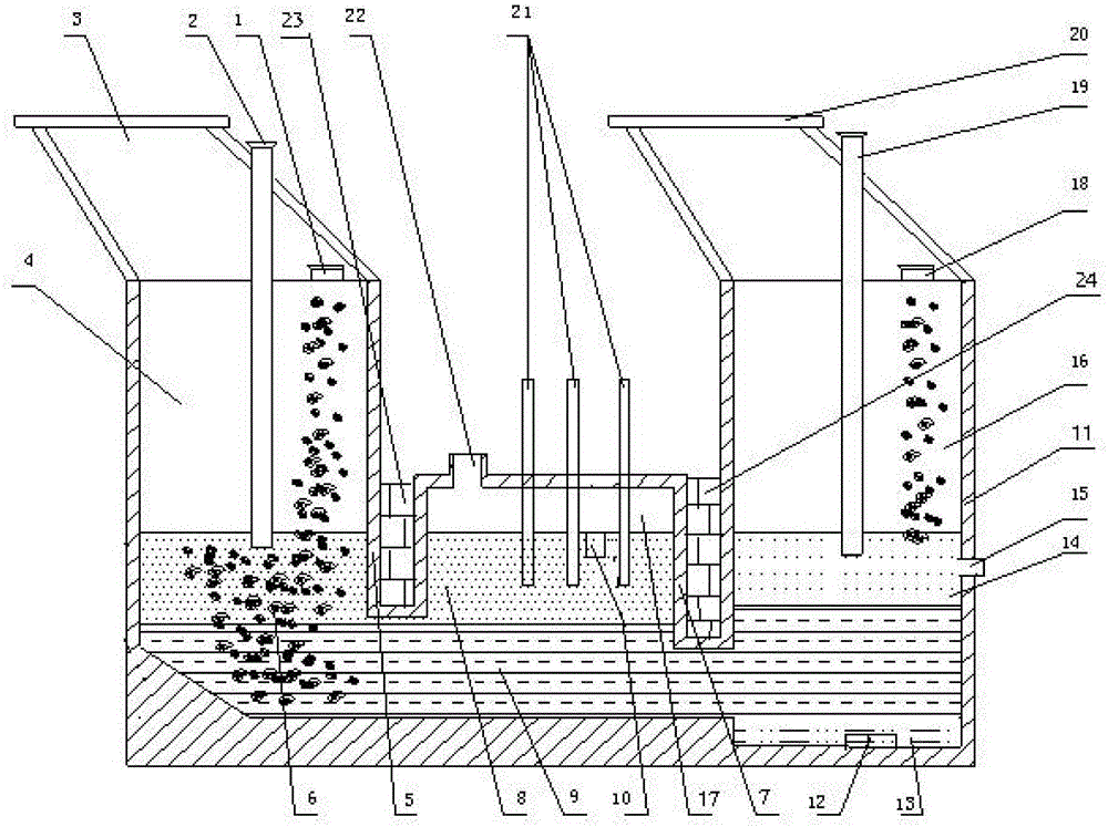
[0017] Such as figure 1The smelting furnace for continuously smelting blister copper with copper sulfide concentrate shown is an integrated metallurgical furnace with top-blown smelting at the front end, electric furnace settling in the middle, and continuous matte blowing at the end. Submerged electric furnace, terminal matte continuous blowing furnace; the front-end top-blown smelting furnace includes a smelting zone furnace body 5 with a copper sulfide concentrate inlet 1 on the top, and a copper sulfide concentrate inserted into the smelting zone furnace 4 from the top of the smelting zone furnace body. The ore smelting spray gun 2, the smelting flue gas outlet 3 arranged on the top of the furnace body in the smelting area; The top of the furnace body is inserted into the electrode 21 of the hearth 17 of the electric furnace area, and the smoke discharge port 22 of the subsidence electric furnace area is arranged on the top of the furnace body of the electric furnace area;...


PUM


Abstract

The invention provides a smelting furnace for continuously smelting blister copper through copper sulfide concentrate and a smelting method of the smelting furnace. The smelting furnace is an integrated metallurgical furnace with the front-end top-blown smelting function, the middle electric furnace setting function and the tail-end matte continuous converting function and comprises a front-end top-blown smelting furnace, a middle setting electric furnace and a tail-end matte continuous converting furnace with the bottoms communicated sequentially. According to the smelting method, the procedures that the copper sulfide concentrate is continuously smelted into mixed melt of matte and slag through the converting furnace, settling separation of the matte and the slag is performed continuously, and the matte is continuously blown into blister copper are not needed. The three metallurgical processes that the copper sulfide concentrate is smelted into the mixed melt of the matte and the slag, settling separation of the matte and the slag is performed, and the matte is continuously blown into the blister copper can be continuously finished, the equipment structure and the operation process are simple, energy consumption is low, and environmental friendliness and safety are achieved.

Description

technical field [0001] The invention relates to nonferrous metal metallurgical equipment and method technology, in particular to pyrometallurgical equipment and method for copper sulfide concentrate. Background technique [0002] The method of smelting copper sulfide concentrate to produce copper is generally divided into two main smelting production process steps. The first step is to smelt copper sulfide concentrate into matte and low copper slag, and the second step is to blow smelt matte into crude copper. The traditional copper smelting process is smelting copper concentrate with blast furnace and blowing matte into blister copper with reverberatory furnace, which is characterized by simple process method, small scale, high energy consumption, high labor intensity and serious environmental pollution. [0003] Focusing on the two central issues of air pollution prevention and control and energy conservation, many new copper smelting processes with their own characterist...

Claims


Application Information

Patent Timeline
IPC IPC(8): C22B15/00
Inventor 宋兴诚袁海滨
Owner YUNNAN TIN
Learn More