
Mechanical shock method and device for effectively reducing laser cladding cracks

A technology of laser cladding and mechanical impact, applied in the direction of metal material coating process, coating, etc., can solve the problems affecting the large-scale application of laser cladding, forming cracks in molded parts, and cladding layer cracks, etc., to suppress thermal cracks and the generation and expansion of cold cracks, the increase of strength, and the effect of fine structure

Active Publication Date: 2015-11-25
YANSHAN UNIV
View PDF4 Cites 5 Cited by
  • Summary
  • Abstract
  • Description
  • Claims
  • Application Information

AI Technical Summary

Problems solved by technology

However, since the melting, solidification and cooling of the material are carried out under extremely fast conditions, it is easy to form defects such as cracks, pores and inclusions in the molded parts.
The most difficult problem to solve in laser cladding is the crack problem of the cladding layer, which has seriously affected the large-scale application of laser cladding in industrial production.

Method used


Image

  • Mechanical shock method and device for effectively reducing laser cladding cracks
  • Mechanical shock method and device for effectively reducing laser cladding cracks
  • Mechanical shock method and device for effectively reducing laser cladding cracks

Examples


Embodiment 1

[0029]On the 20CrMnTi steel shaft base material with a diameter of 20mm, carry out the laser cladding coating of Fe90 self-fluxing alloy powder+TiC powder, the used cladding self-fluxing alloy powder (chemical composition percentage Wt% is: 13.6Cr, 1.6 B, Si1.2, Mo0.8, C0.8, Fe balance), add TiC with a mass fraction of 5%, mix it evenly with a three-dimensional mixing agitator, dry it in a dryer, and add it to the powder feeder stand-by. Carry out turning treatment on the surface of the substrate, clean the fatigue layer, holes, cracks, etc. on the surface, clean the surface with acetone or alcohol, and clamp the workpiece with the three-jaw chuck of the CNC bed. Apply mechanical impact on the single track where the workpiece has been clad, and input the relevant parameters in the numerical control system, in which the shaft surface line speed is 250mm / min, the lap rate is 40%, the powder feeding speed of the powder feeder is controlled to 80g / min, the gas The flow rate is 5l...

Embodiment 2

[0031] The methods are the same as in Example 1, except that the mechanical shock frequency is 300 Hz, L1 is 10 mm, and L2 is 15 mm during laser cladding. Depend on Figure 9 It can be seen that the structure is uniform, the arrangement is orderly, the grains are more refined, and the pores basically disappear.

[0032] It is known from the above two examples that the number of various defects (pores, cracks, etc.) of the cladding layer is suppressed when the mechanical impact is assisted, thereby improving the performance of the cladding layer. It has been verified that the impact of mechanical impact on laser melting The cladding layer can effectively reduce cladding layer cracks and improve the effect of cladding layer structure.


PUM


Abstract

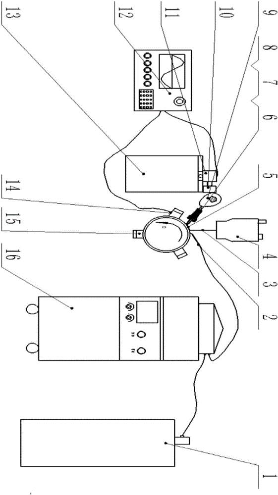
A mechanical shock device for effectively reducing laser cladding cracks mainly comprises a powder feeding type high-power semiconductor laser cladding device, a numerical control device and a mechanical shock assembly. According to the mechanical shock device, a workpiece to be subjected to fusion cladding is clamped through a three-jaw chuck or a four-jaw chuck, powder is fed to the workpiece in a preset powder feeding mode, mechanical shock with a certain frequency is applied to a single channel where laser cladding is completed, and a fusion cladding layer with excellent quality is obtained. Since dendritic crystals which are separated out preferentially in a molten pool can be effectively broken into pieces through mechanical vibration caused by the shock, crystal grains are refined, the plasticity of solidified crystals is improved, and heat cracks are avoided; moreover, under the hammering action of a mechanical shock hammer on the cladding single channel, residual tension produced in the cooling process of the molten pool can be partially balanced out, cold cracks are reduced, and the fusion cladding layer with the excellent quality is obtained.

Description

technical field [0001] The invention relates to a method and device for processing materials, in particular to a method and device for processing laser cladding materials. Background technique [0002] Laser cladding technology is a rapidly developing surface processing technology and an emerging technology in material processing. Using a high-energy laser beam, the metal powder and the substrate are rapidly melted and cooled, and the two interact to finally obtain a surface with high hardness and wear resistance that is difficult to obtain by conventional methods. However, since the melting, solidification and cooling of materials are carried out under extremely fast conditions, it is easy to form cracks, pores, inclusions and other defects in the formed parts. The most difficult problem to solve in laser cladding is the crack problem of the cladding layer, which has seriously affected the large-scale application of laser cladding in industrial production. Contents of th...

Claims


Application Information

Patent Timeline
Patent Type & Authority Applications(China)
IPC IPC(8): C23C24/10
Inventor 郑丽娟王好平谢亮黄浩杜文连王祺
Owner YANSHAN UNIV
Learn More