
Power transmission module for a motor vehicle

A transmission system and motor vehicle technology, applied in the field of transmission system modules, can solve problems affecting KSG efficiency, etc., and achieve the effects of compact structure, improved efficiency, and reduced radial motion

Active Publication Date: 2015-11-25
MAN TRUCK & BUS AG
View PDF6 Cites 2 Cited by
  • Summary
  • Abstract
  • Description
  • Claims
  • Application Information

AI Technical Summary

Problems solved by technology

However, the increased gap height adversely affects the efficiency of KSG

Method used


Image

  • Power transmission module for a motor vehicle
  • Power transmission module for a motor vehicle
  • Power transmission module for a motor vehicle

Examples


Embodiment Construction

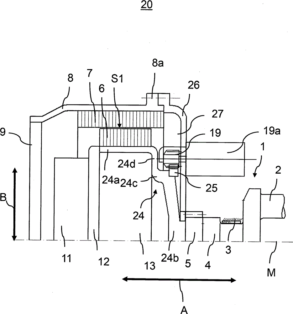
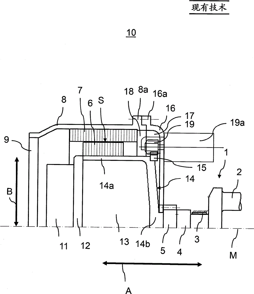
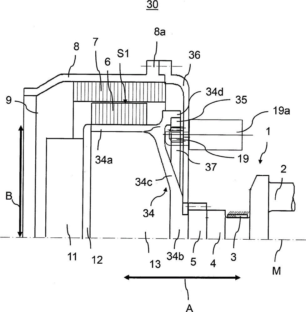
[0087] exist Figures 1 to 4 In each case only the upper half of the drive train module is shown in side view.

[0088] figure 1 A known drive train module for a commercial vehicle is shown. The centerline of the crankshaft is shown with a dotted line M. exist figure 1 Only part of the crankshaft 1 is visible in the figure, in particular the crankshaft bearing 3 , the crank pin 2 for receiving the connecting rod, the flange area 4 and the gear wheel 5 . Via gear 5 , the camshafts can be actuated with defined transmission ratios.

[0089] A cup-shaped flywheel 14 is connected to the crankshaft 1 . The flywheel 14 includes a hollow-cylindrical outer edge region 14 a which extends on the transmission side and on which the annular rotor 6 of the crank-starter generator is arranged in a rotationally fixed manner. The transmission on the output side is not shown, which is in the figure 1 The center is arranged on the left of the drive train module 10 .

[0090] Furthermore, ...


PUM


Abstract

The invention relates to a drive train module for a motor vehicle, comprising a to the crankshaft (1) connected to said flywheel (24); one connected to the crankshaft (1) operatively connected to a crankshaft starter generator, comprising a rotor (6) and a stator (7); a flywheel (24) arranged ring gear (25) and an electric starter motor (19a) with a starter pinion (19) which is engaged to rotate the ring gear with this can be brought and / or is engaged, wherein the starter pinion in a radial direction, perpendicular to the crankshaft axis (M) is offset with respect to the rotor (6) and / or the stator (7) is arranged the crankshaft starter generator.

Description

technical field [0001] The invention relates to a drive train module for a motor vehicle, in particular an assembly consisting of a flywheel and a crankshaft starter generator. Background technique [0002] In order to enable the first mixture formation, ignition and combustion in the internal combustion engine, the internal combustion engine is brought to a defined minimum rotational speed by an external force source. For this purpose, drive train modules are known from the prior art in which an electric crank-starter generator (KSG) is arranged between the engine and the transmission. This is an electric motor with starter and generator functions on the crankshaft, which is often referred to as a crankshaft-starter generator because its rotor is directly coupled to the crankshaft of the internal combustion engine. [0003] The KSG rotor is connected to the flywheel arranged on the crankshaft. In this way it is in operative connection with the crankshaft. The connected a...

Claims


Application Information

Patent Timeline
Patent Type & Authority Applications(China)
IPC IPC(8): F02N15/00F02N11/04B60L50/16
CPCF02N11/04B60K6/485B60L11/14F02N11/006F02N2300/2002F16F15/30H02K7/006B60L3/0061B60L15/20B60L50/16B60L2220/50B60L2240/36B60L2240/421B60L2240/441B60L2260/26Y02T10/62Y02T10/64Y02T10/7072Y02T10/72
Inventor W.布克哈特
Owner MAN TRUCK & BUS AG
Learn More