

Closed gas stove
A gas stove and closed type technology, applied in the field of closed combustion gas stoves, can solve the problems of inability to fully conduct flue gas from the cooker, impossible to achieve energy saving, heat loss, etc. Effect
- Summary
- Abstract
- Description
- Claims
- Application Information
AI Technical Summary
Problems solved by technology
Method used
Image

Examples
Embodiment 1
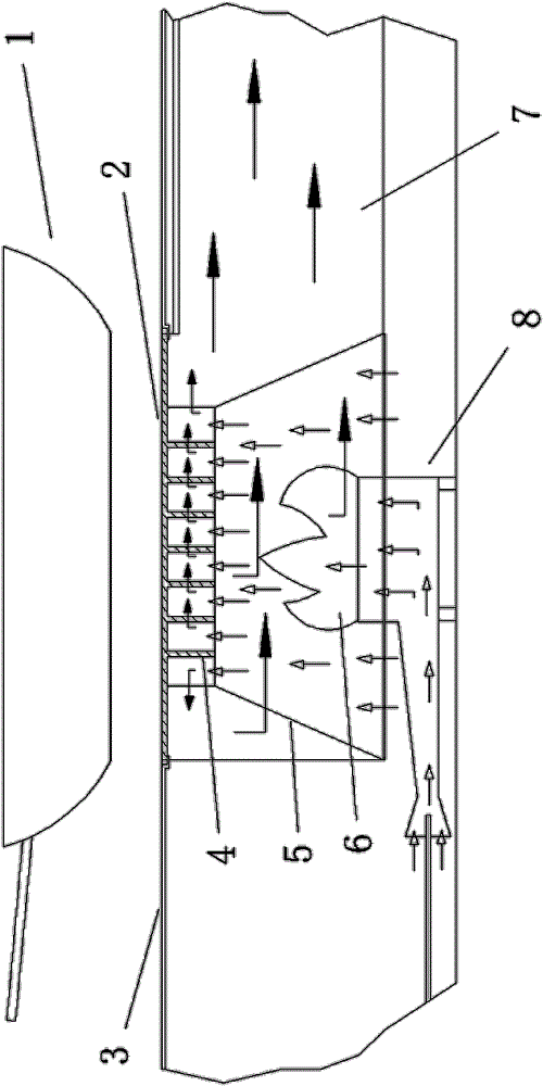
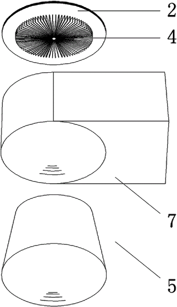
[0032] Embodiment one: figure 1 A burner (8) is provided in the cavity of the middle stove, and a combustion chamber jacket (5) is arranged around the immediate top of the burner (8), forming a semi-closed combustion chamber. The combustion chamber jacket (5) and the burner ( 8) The space between them is open, and the secondary air enters the combustion chamber from here. The lower side of the combustion chamber casing (5) is inlaid with the shell of the flue member (7), and a conical space is formed between the two. The combustor jacket (5) also isolates the combustion chamber from the exhaust passage, the combustor jacket (5) is connected to the heat spreader fins (4), and the heat spreader fin group (4) is integrated with the heat conduction block (2) structure, (see figure 2 It can be seen that the heat spreader fins (4) are radially combined and connected to one side of the heat conduction block (2). Grooves are formed between the fins, and the heat conduction block (2...
Embodiment 2
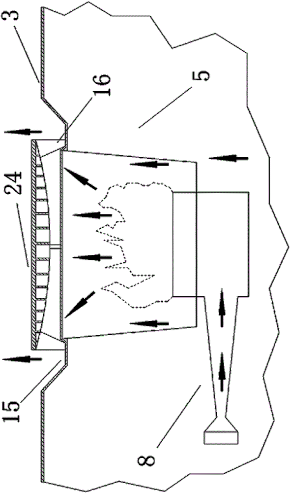
[0033] Embodiment two: image 3 In this case, the heat spreader (24) is still set directly above the flame (6) of the burner (8), its exposed end (heat spreader panel) is slightly higher than the cooker panel (3), and the gap forms a straight flue , the outer periphery of the flame is provided with a combustion chamber (5) to form a combustion chamber, and the upper side of the combustion chamber (5) is connected with fins or a water tray (15) to prevent smoke from entering the kitchen cavity. The premixed gas is ejected from the burner (8), and the secondary air enters from the gap between the bottom of the combustor jacket (5) and the burner, and the hot smoke generated by the flame rises and first touches the heat conductor (24 ), and stick to the heat spreader (24) and continue to discharge out of the stove along the gap, the heat spreader (24) quickly becomes very The hot, rising flue gas around forms an oxygen isolation ring, which protects the outer surface of the heat...
PUM
 Abstract
Description
Claims
Application Information