Comprehensive treatment method for iron ore sintering smoke pollutants

A technology for sintering flue gas and comprehensive treatment, applied in waste heat treatment, separation methods, chemical instruments and methods, etc., can solve the problems of low flue gas circulation ratio, low efficiency of desulfurization system, low concentration, etc., and achieve energy saving. Effect

Active Publication Date: 2015-11-25
CENT SOUTH UNIV
View PDF6 Cites 25 Cited by
  • Summary
  • Abstract
  • Description
  • Claims
  • Application Information

AI Technical Summary

Problems solved by technology

④High water vapor content
⑦ SO in the large sintering flue 2 Low concentration, resulting in low desulfurization system efficiency
At the same time, the flue gas circulation technology currently used in the

Method used


Image

  • Comprehensive treatment method for iron ore sintering smoke pollutants

Examples


Embodiment 1

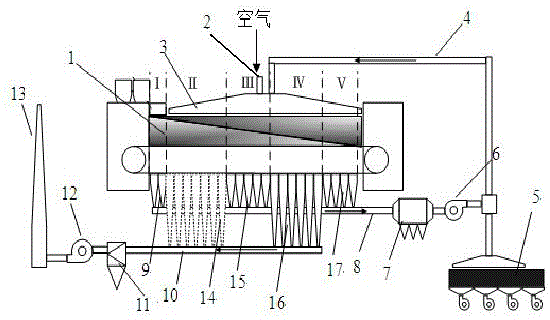
[0021] A comprehensive treatment method for iron ore sintering flue gas pollutants of the present invention, the specific process is as follows: in the sintering granulation process, on the basis of the heat released by the digestion of quicklime in the sintering material, the sintering high-temperature steam is used to preheat the mixed material, The temperature of the sintered material reaches 80°C; the nine-roller material distribution technology is used in the material distribution, so that the content of coke powder in the sintered bottom layer material is 0.4% lower than that of the surface layer material; there are 24 bellows in the sintering machine, and the sintering end is reached in the 22nd bellows, and the machine head The flue gas of No. 1~2 wind boxes (Area Ⅰ), No. 11~14 wind boxes in the machine (Zone III) and No. 21~24 wind boxes (Zone V) at the rear of the machine are circulated to the sintered material surface of the sintering machine, and the flue gas circula...

Embodiment 2

[0023] A comprehensive treatment method for iron ore sintering flue gas pollutants of the present invention, the specific process is as follows: in the sintering granulation process, on the basis of the heat released by the digestion of quicklime in the sintering material, the sintering high-temperature steam is used to preheat the mixed material, The temperature of the sintered material reaches 90°C; the nine-roller material distribution technology is used in the material distribution, so that the content of coke powder in the sintered bottom layer material is 0.8% lower than that of the surface layer material; there are 24 bellows in the sintering machine, and the sintering end is reached in the 22nd bellows, and the machine head The flue gas of No. 1~2 wind boxes (Area Ⅰ), No. 11~14 wind boxes in the machine (Zone III) and No. 21~24 wind boxes (Zone V) at the rear of the machine are circulated to the sintered material surface of the sintering machine, and the flue gas circula...


PUM


Abstract

The invention provides a comprehensive treatment method for iron ore sintering smoke pollutants. According to the characteristic that the properties of sintering smoke at different positions of a sintering machine are different, the sintering machine is sequentially divided into a section I, a section II, a section II, a section IV and a section V from the machine head to the machine tail. The length of the section I accounts for one twelfth that of the sintering machine. The length of the section II accounts for one fourth to three tenths that of the sintering machine. The length of the section III accounts for one fifth to one fourth that of the sintering machine. The length of the section IV accounts for one fourth of the sintering machine. The length of the section V accounts for one sixth that of the sintering machine. Smoke in the section I, the section III and the section V circulates to a smoke hood of the sintering machine through a circulating flue. The proportion of circulating smoke is 45%-50%. According to the features of the smoke entering the sintering bed layer, the temperature is 200 DEG C-250 DEG C, the content of O2 is greater than or equal to 17%, the content of CO2 is less than or equal to 6%, H2O (g) is less than or equal to 8%, and the content of SO2 is less than or equal to 500 ppm. The smoke in the section II and the smoke in the section IV are treated by a comprehensive activated carbon desulfurization and denitrification system and then discharged.

Description

technical field [0001] The invention relates to a method for energy saving and emission reduction in the iron ore sintering process, in particular to a comprehensive treatment method for iron ore sintering flue gas pollutants. Background technique [0002] The iron ore sintering process is the main source of flue gas pollutants in the iron and steel industry, and its exhaust gas emissions account for 40% of the total exhaust gas in the iron and steel industry. The sintering flue gas is the dust-containing waste gas generated during the high-temperature sintering molding process with the operation of the trolley after the mixture is ignited. Its main characteristics are: ①Due to the influence of air leakage and high return rate, the amount of sintering flue gas is relatively large. Large, about 4000~6000m3 for every 1t of sinter produced 3 smoke. ②The temperature of the sintering flue gas is relatively high, especially in several bellows near the end of sintering. The flue...

Claims


Application Information

Patent Timeline
IPC IPC(8): F27D17/00B01D50/00B01D53/50B01D53/56
CPCY02P10/25
Inventor 范晓慧甘敏余志元陈许玲姜涛李光辉季志云周阳黄晓贤吕薇袁礼顺郭宇峰杨永斌黄柱成李骞张元波朱忠平许斌何向宁李强王英坡
Owner CENT SOUTH UNIV
Why Eureka
Try Eureka