
Groove and microstructure composite liquid absorption core and manufacturing method thereof

A manufacturing method and microstructure technology, which are applied in the field of liquid absorbent cores to achieve the effects of weight reduction, good comprehensive capillary performance and light weight

Inactive Publication Date: 2015-11-25
SOUTH CHINA UNIV OF TECH
View PDF6 Cites 12 Cited by
  • Summary
  • Abstract
  • Description
  • Claims
  • Application Information

AI Technical Summary

Problems solved by technology

[0005] The purpose of the present invention is to address the shortcomings of the current commonly used single liquid-absorbent core structure, and propose a groove and microstructure composite liquid-absorbent core and its manufacturing method. The composite liquid-absorbent core has high capillary pressure and permeability at the same time, and has Good comprehensive capillary performance

Method used


Image

  • Groove and microstructure composite liquid absorption core and manufacturing method thereof
  • Groove and microstructure composite liquid absorption core and manufacturing method thereof
  • Groove and microstructure composite liquid absorption core and manufacturing method thereof

Examples


Embodiment 1

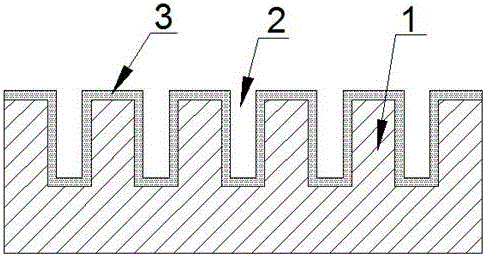
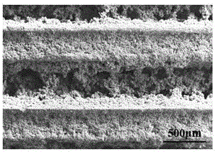
[0032] Such as figure 1 As shown, a groove and microstructure composite liquid-absorbing core includes a copper substrate 1 with grooves processed on the surface, and the inner surface of the groove and the outer surface of the copper substrate 1 processed with grooves are all provided with a thickness of 0.1-1000 μm microstructure layer 3, the microstructure 3 covers all the surface of the trench, but does not fill the trench, there are still gaps 2 between the walls of the trench, the microstructure layer 3 is mainly composed of particles It is composed of fine copper particles with a diameter between 0.1 and 20 μm, and tiny pores of 1 to 100 μm are formed between the fine copper particles.

[0033] Specifically, the cross-sectional shape of the groove in this embodiment is V-shaped, rectangular, trapezoidal or arc-shaped, or other irregular shapes, and the cross-sectional shape of the groove in this embodiment is rectangular.

[0034] Specifically, the maximum width of th...

Embodiment 2

[0037] A method for manufacturing a groove and microstructure composite liquid-absorbent core as described, comprising the following steps and process conditions:

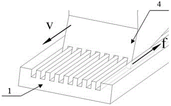
[0038] (1) Using the planing process and the multi-tooth cutter 4 to process a plurality of groove structures on the copper plate substrate 1;

[0039] (2) After cleaning the groove structure, use the electrochemical deposition method to build a microstructure on the surface of the groove as the cathode. Before the electrochemical deposition, the groove base needs to be cleaned ultrasonically. The cleaning time is about 5 minutes. The cleaning solution is cleaned with ethanol and a mixture of deionized water;

[0040] (3) Improve the interfacial bonding strength between the microstructure and the groove surface by sintering and curing process.

[0041] Specifically, the electrolytic solution used in the electrochemical deposition described in this implementation is a solution CuSO containing copper ions. 4 , the ...

Embodiment 3

[0045] A method for manufacturing a groove and microstructure composite liquid-absorbent core as described, comprising the following steps and process conditions:

[0046] (1) Using the planing process and the multi-tooth cutter 4 to process a plurality of groove structures on the copper plate substrate 1;

[0047] (2) After cleaning the groove structure, use the electrochemical deposition method to build a microstructure on the surface of the groove as the cathode. Before the electrochemical deposition, the groove base needs to be cleaned ultrasonically. The cleaning time is about 5 minutes. The cleaning solution is cleaned with ethanol and a mixture of deionized water;

[0048] (3) Improve the interfacial bonding strength between the microstructure and the groove surface by sintering and curing process.

[0049] Specifically, the electrolytic solution used in the electrochemical deposition described in this implementation is a solution CuCl containing copper ions. 2 , the co...


PUM

PropertyMeasurementUnit
thicknessaaaaaaaaaa
particle diameteraaaaaaaaaa
widthaaaaaaaaaa

Abstract

The invention discloses a groove and microstructure composite liquid absorption core. The groove and microstructure composite liquid absorption core comprises a red copper basal body provided with a groove in the surface, wherein microstructure layers with thicknesses of 0.1-1000 microns are respectively arranged on the inner surface of the groove and the outer surface, provided with the groove, of the red copper basal body; and the microstructure layers mainly consist of fine copper particles with particle sizes within 0.1-20 microns. The invention further discloses a manufacturing method of the composite liquid core; and the method comprises the following steps: (1) the groove structure is machined on the red copper basal body by a broaching or planing process; (2) after the groove structure is cleaned, the microstructure is built on the surface of the groove as a cathode by an electrochemical deposition method; and (3) the interface bonding strength between the microstructure and the surface of the groove is improved through a sintering curing process. The composite liquid absorption core, provided by the invention, can provide excellent capillary force, is excellent in permeability, and facilitates to flow liquid on a condensation section back to an evaporation section; and the manufacturing method is simple, easy to be controlled, high in production efficiency and low in cost, and can be widely applied to such two-phase heat transfer devices as heat pipes, heat columns and soaking plates.

Description

technical field [0001] The invention relates to a liquid-absorbing core, in particular to a groove and microstructure composite liquid-absorbing core for a two-phase heat transfer device and a manufacturing method thereof. Background technique [0002] Two-phase heat transfer devices such as heat pipes, heat columns, and vapor chambers have the advantages of high thermal conductivity, fast thermal response, and no need for external driving force. They have been widely used in heat dissipation systems for high heat flux electronic products. With the rapid development of microelectronics manufacturing technology, the heat flux density of electronic chips will increase greatly, which puts forward higher requirements for the heat transfer performance of two-phase heat transfer devices. In the two-phase heat transfer device, the working fluid in the evaporation section is heated and evaporated into gas and enters the condensation section under the action of pressure difference. T...

Claims


Application Information

Patent Timeline
Patent Type & Authority Applications(China)
IPC IPC(8): F28D15/04
Inventor 汤勇刘侨鹏陆龙生申众孚李斌
Owner SOUTH CHINA UNIV OF TECH
Learn More