
Fiber grating temperature measurement system and method for high overload distribution transformer

A distribution transformer and optical fiber grating technology, which is applied in the field of distribution transformer life cycle prediction, can solve the problem that the sensitivity and accuracy of temperature measurement cannot accurately reflect the continuous change of hot spot temperature rise of high overload distribution transformer windings and the fluctuation of load curve in real time Large and other problems, to achieve the effect of reducing computational complexity, efficient prediction, and improving computational efficiency

Inactive Publication Date: 2015-11-25
ELECTRIC POWER RESEARCH INSTITUTE OF STATE GRID SHANDONG ELECTRIC POWER COMPANY +2
View PDF5 Cites 4 Cited by
  • Summary
  • Abstract
  • Description
  • Claims
  • Application Information

AI Technical Summary

Problems solved by technology

Distribution transformers are directly connected to users, and their load curves fluctuate greatly, especially the distribution transformer load in rural power grids has irregular time-varying characteristics. The existing patent "Method for Transformer Life Prediction Based on Fiber Bragg Grating In terms of temperature sensitivity and accuracy, it is not able to reflect the process of continuous change of hot spot temperature rise of high overload distribution transformer windings in real time and accurately.

Method used


Image

  • Fiber grating temperature measurement system and method for high overload distribution transformer
  • Fiber grating temperature measurement system and method for high overload distribution transformer
  • Fiber grating temperature measurement system and method for high overload distribution transformer

Examples


Embodiment Construction

[0037] The present invention is described in detail below in conjunction with accompanying drawing:

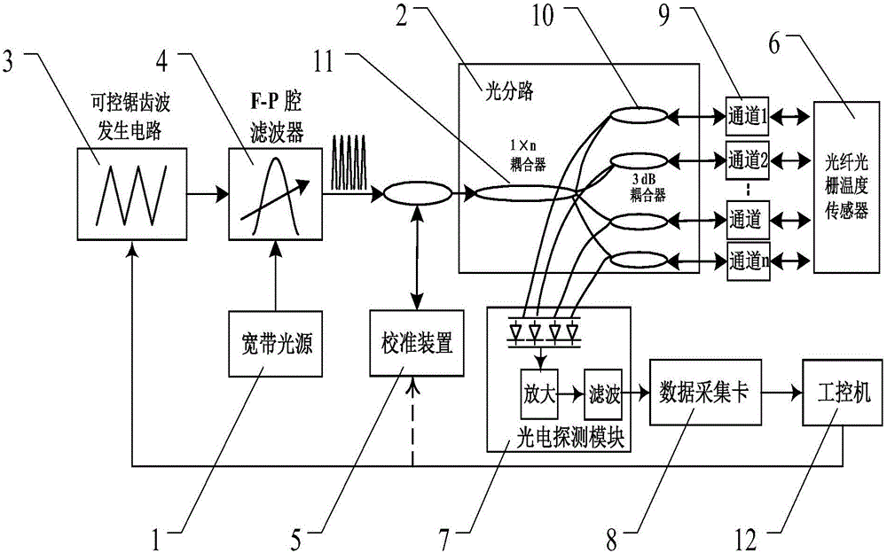
[0038] Such as figure 1 As shown, the fiber grating temperature measurement system of high overload distribution transformer is mainly composed of broadband light source 1, optical splitter 2, controllable sawtooth wave generation circuit 3, F-P cavity filter 4, calibration device 5, grating temperature sensor 6, It consists of a photoelectric detection module 7 and a data acquisition card 8. Among them, the broadband light source 1 provides the system with continuous scanning narrow-band spectrum; the function of optical splitter 2 is to divide the continuous spectrum emitted by the light source into the required number of optical paths; the F-P cavity filter 4 is driven by a controllable sawtooth wave voltage for Demodulate the signal of the sensing grating; the calibration device 5 is used to determine the relationship between the voltage of the adjustable light source and...


PUM


Abstract

The invention discloses a fiber grating temperature measurement system and method for a high overload distribution transformer. The system comprises: a broadband light source; a controllable sawtooth wave generating circuit; an F-P cavity tunable filter, used for demodulating narrow band spectra generated by the broadband light source into astigmatic spectral signals according to the drive of a sawtooth wave voltage output by the sawtooth wave generating circuit; an optical splitter, used for splitting the astigmatic spectral signals output by the F-P cavity tunable filter to a required number of optical paths and communicating with a fiber grating temperature sensor; a calibration device, used for determining the relation between the voltage of the tunable light source and the central wavelength in real time; and a photoelectric detection module, used for converting reflected wave reflected by each sensing grating and uniquely corresponding to the sensing grating from an optical signal to an electrical signal and transmitting the electrical signal to a data acquisition card. By utilizing a quasi-distributed fiber grating temperature measurement technology, high-precision measurement of hot-spot temperature of the high overload distribution transformer is realized, and aging evaluation and remaining life cycle prediction of the high overload distribution transformer are realized.

Description

technical field [0001] The invention relates to an on-line monitoring technology for power transmission and distribution equipment, more specifically, uses a quasi-distributed optical fiber grating temperature sensor to measure the hot spot temperature of a power distribution transformer and predict the life cycle of the power distribution transformer. Background technique [0002] The rural power grid has the characteristics of load dispersion, strong seasonality, low average load rate, and large peak-to-valley difference. From the analysis of operation conditions, the load of rural power grids increases rapidly during special periods (such as Spring Festival and busy farming seasons). Short-term overload and heating problem is very prominent. The hot spot temperature of the inner winding of the transformer is directly related to its insulation performance and aging life. Exceeding the allowable value of the temperature will reduce the service life of the transformer, espec...

Claims


Application Information

Patent Timeline
Patent Type & Authority Applications(China)
IPC IPC(8): G01K11/32G01K11/3206G01K11/322G01K11/324
Inventor 蒋斌李荣李立生李红梅张林利石鑫王华广董啸刘明林房牧
Owner ELECTRIC POWER RESEARCH INSTITUTE OF STATE GRID SHANDONG ELECTRIC POWER COMPANY
Learn More