Optical power and gain detection device and method in optical amplifier burst mode

A technology of optical amplifier and burst mode, which is applied in the field of optical communication, can solve problems such as inability to obtain accurate gain, affect cost and performance, and increase system design complexity, so as to increase temperature detection circuit and compensation coefficient, and accurately calculate amplifier Effect of gain and stable detection optical power

Active Publication Date: 2017-03-22
GUANGXUN SCI & TECH WUHAN
View PDF6 Cites 4 Cited by
  • Summary
  • Abstract
  • Description
  • Claims
  • Application Information

AI Technical Summary

Problems solved by technology

Since the microcontroller can only operate serially, the input and output optical power cannot be sampled at the same time, so for the burst mode, accurate gain cannot be obtained
[0007] In the prior art, the detection of burst mode optical power and gain can be realized through both analog and digital aspects, and different detection devices and methods affect cost and performance
For example, the patent "On-line Optical Power Detection Device at Receiver and Its Implementation Method" (Patent No. 201110200643.7) needs to add BNC terminals and other acquisition modules to the general ONU module, and additional trigger signals need to be added to the algorithm itself; Method and system for measuring optical power in burst mode" (Patent No. 200610093150.7) adopts the method of adding a current mirror, and the analog circuit is complicated, which is not conducive to the use of optical amplifiers
The implementation methods in the prior art all need to modify the ONU module, or even modify the algorithm, which increases the complexity of the system design and does not meet the development needs of the current broadband communication system.

Method used


Image

  • Optical power and gain detection device and method in optical amplifier burst mode
  • Optical power and gain detection device and method in optical amplifier burst mode
  • Optical power and gain detection device and method in optical amplifier burst mode

Examples


Embodiment Construction

[0049] In order to make it easier for those skilled in the art to understand and implement the present invention, the present invention will be further described in detail below in conjunction with the accompanying drawings and specific embodiments.

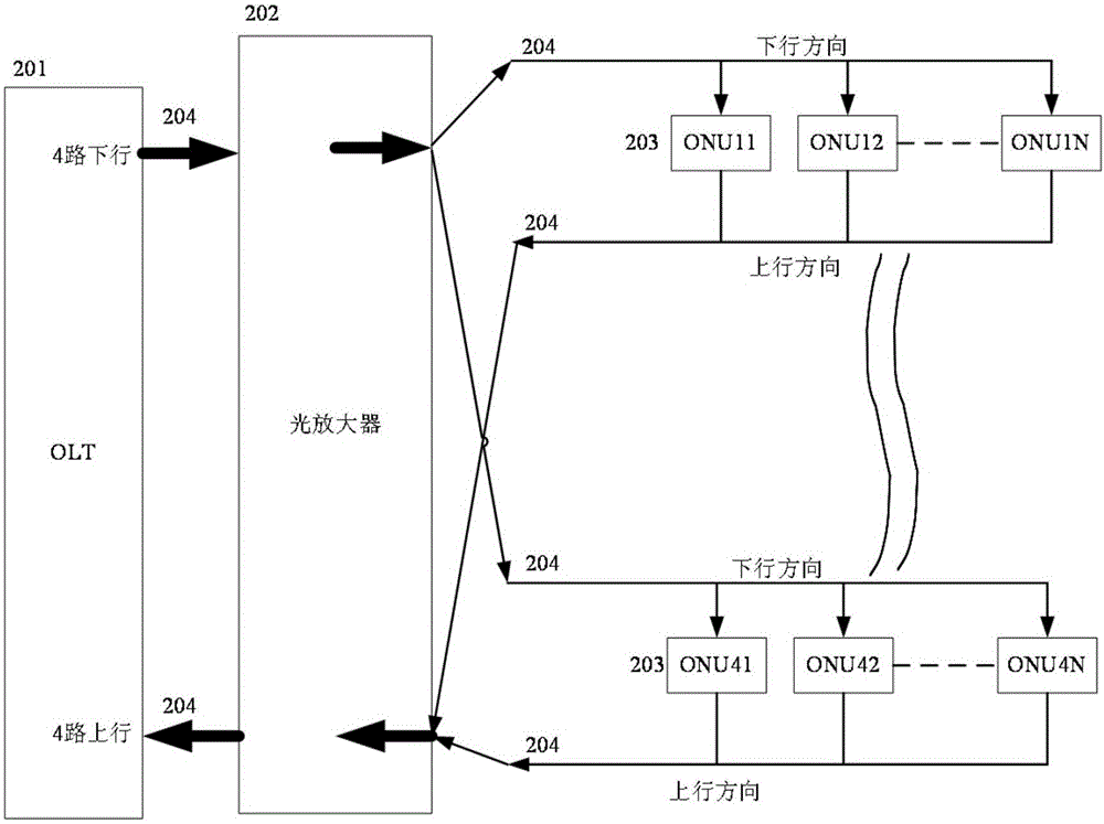
[0050] A typical PON system is simplified as figure 1 As shown, it mainly includes: OLT unit 201, optical amplifier 202, multiple ONU units 203, and fiber optic cable 204; in order to increase the transmission distance and improve the signal-to-noise ratio, the OLT unit 201 and the ONU (that is, multiple ONU units 203) An optical amplifier 202 is provided between them. The uplink port and downlink port of the OLT unit 201 are four ports, therefore, the corresponding optical amplifier 202 must also support the detection and amplification of four uplink signals and downlink signals at the same time (that is, it needs to support the detection and amplification of 8-way signals). Wherein, each downlink output port of OLT unit 201 (s...


PUM


Abstract

The invention provides an optical power and gain detection device and method in an optical amplifier burst mode. The optical power and gain detection device used in an optical amplifier burst mode comprises a plurality of optical power detecting circuits, a FPGA device and a temperature detecting circuit, wherein each optical power detection circuit has the same structure and the realization mode, comprising a respectively independent photoelectric converter, a transconductance circuit, an analog signal conditioning circuit, a filter and an analog to digital conversion chip. Through the improvement of the analog circuit, the digital detection and the control in the conventional optical amplifier, and the using of the characteristics of the FPGA device, the detection of the optical signal and gain in the burst mode is realized by means of the algorithm. By means of the optical power and gain detection device and method in the optical amplifier burst mode, the addition of complex analog circuits is avoided, and meanwhile, the influence of the inconsistency of the components in the analog control scheme is avoided, therefore, the algorithm can detect the optical power accurately and steadily regardless of whether the optical signal is in the stable mode or the burst mode, and the range of application is wide; and the amplifier gain can be calculated more accurately by strictly controlling the synchronization of ADC sampling and the computing delay.

Description

technical field [0001] The invention relates to optical communication technology, in particular to the improvement of the optical amplifier, in particular to a device and method for detecting optical power and gain in the burst mode of the optical amplifier. The invention is used to solve the problem of detection of optical power and gain by optical amplifiers in the field of communication, and is mainly used to accurately detect optical power and gain in burst mode in the field of broadband optical fiber passive optical network access Background technique [0002] The access network is the bridge for users to enter the MAN / backbone network, and is the "last mile" of the information transmission channel. With the gradual emergence of the Internet and high-bandwidth consuming services, bandwidth acceleration has become an urgent need. In order to meet the needs of users, various new technologies are constantly emerging, and access network technology has become the focus of r...

Claims


Application Information

Patent Timeline
Patent Type & Authority Applications(China)
IPC IPC(8): H04B10/079
CPCH04B10/0795H04B10/07955H04B10/0797H04B10/291H03G3/3084H04B10/2931H04J14/0221
Inventor 于龙张蔚青李春雨陈志余春平卜勤练
Owner GUANGXUN SCI & TECH WUHAN
Why Eureka
Try Eureka