Magnetic field detecting sensor and magnetic field detecting apparatus using the same

A technology for detecting sensors and magnetic fields, applied in measurement devices, instruments, measuring magnetic variables, etc., can solve the problems of reducing manufacturing costs and miniaturizing sensors, and achieve the effect of reducing manufacturing costs and suppressing product costs.

Active Publication Date: 2015-11-25
TDK CORPARATION
View PDF10 Cites 10 Cited by
  • Summary
  • Abstract
  • Description
  • Claims
  • Application Information

AI Technical Summary

Problems solved by technology

In addition, there are general issues such as reduction of manufacturing costs and miniaturization of sensors.

Method used


Image

  • Magnetic field detecting sensor and magnetic field detecting apparatus using the same
  • Magnetic field detecting sensor and magnetic field detecting apparatus using the same
  • Magnetic field detecting sensor and magnetic field detecting apparatus using the same

Examples


Embodiment approach 1

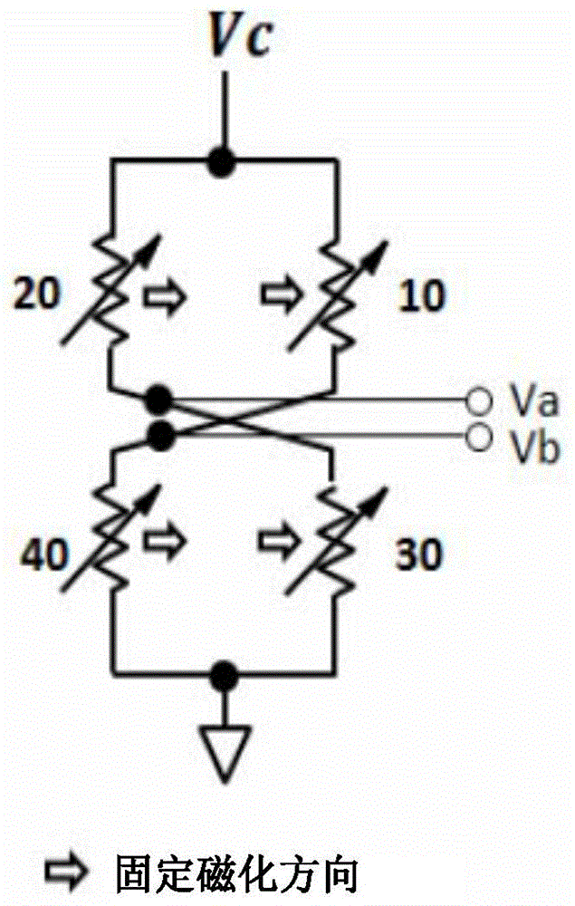
[0045] figure 1 It is a schematic diagram of a bridge circuit constituting the magnetic field detection sensor of the first embodiment. The bridge circuit includes a first magnetoresistance effect element 10, a second magnetoresistance effect element 20, a third magnetoresistance effect element 30, and a fourth magnetoresistance effect element 40. The first to fourth magnetoresistance effect elements (10, 20, 30, 40) have the same fixed magnetization directions. One end of the first magnetoresistance effect element 10 and one end of the second magnetoresistance effect element 20 are connected to the power supply terminal Vc. The other end of the first magnetoresistance effect element 10 is connected to one end of the fourth magnetoresistance effect element 40, and the other end of the second magnetoresistance effect element 20 is connected to one end of the third magnetoresistance effect element 30. The other end of the third magnetoresistance effect element 30 and the other e...

Embodiment approach 2

[0062] Figure 7 with Figure 8 This is a biological field measurement device of the second embodiment as an example of a magnetic field detection device using the above-mentioned magnetic field detection sensor. Since one or more of the above-mentioned magnetic field detection sensors are arranged in contact with the detected part and each output is a small signal, a lock-in amplifier circuit or the like is used for the measurement part for measurement. In addition, in order to remove irregular repetitive signals such as external magnetic fields or spontaneous magnetic fields, analog filters such as band-pass filters or digital processing such as arithmetic averaging may be appropriately used.

[0063] Explanation of symbols

[0064] 1 stack

[0065] 10, 20, 30, 40, 50, 60 magnetoresistive effect element

[0066] 100 magnetic field generating conductor

[0067] 200, 210 terminal pads

[0068] 300 detection resistance

[0069] 400 differential operation circuit


PUM


Abstract

A magnetic field detecting sensor includes a bridge circuit which is connected to multiple magnetoresistive effect elements and is capable of outputting a differential voltage between specified connection points, a magnetic field generating conductor for providing the magnetoresistive effect elements with a magnetic field in a direction opposite to that of the detection magnetic field by disposing a magnetic body near the center of the bridge circuit, a differential operation circuit which the differential voltage is input in and makes a feedback current flow to the magnetic field generating conductor, wherein the feedback current generates the magnetic field in a direction opposite to that of the detection magnetic field in the magnetic field generating conductor, and a voltage converting circuit for outputting the feedback current as a voltage value. The magnetic field generating conductor and the magnetoresistive effect elements are formed in the same stacked body.

Description

Technical field [0001] The present invention relates to a magnetic field detection sensor that uses a magnetoresistance effect element to detect a small magnetic field. Background technique [0002] In recent years, the demand for measuring weak magnetic fields such as biomagnetic field measurement, flaw detection measurement and non-destructive testing has been increasing. [0003] In the measurement of a small magnetic field, it is important to efficiently take the magnetic field of the test object in the direction of the magneto-resistance effect element's magnetic sensitivity. In addition, the resistance change rate of the magneto-resistance effect element changes due to changes in the ambient temperature. In addition, the so-called temperature drift in which the output of the magnetic field detection sensor fluctuates becomes a problem. In addition, general issues such as reduction in manufacturing costs and downsizing of sensors also exist. [0004] According to Patent Docume...

Claims


Application Information

Patent Timeline
Patent Type & Authority Applications(China)
IPC IPC(8): G01R33/09
CPCG01R33/09G01R33/1253
Inventor 小川明宏笠岛多闻田边圭
Owner TDK CORPARATION
Why Eureka
Try Eureka