Single-phase permanent magnet brushless direct-current motor with auxiliary teeth and auxiliary windings

A DC motor, single-phase permanent magnet technology, applied in the field of electric motors, can solve the problems of inability to start smoothly and smoothly, the vibration of the motor is large, and the vibration moment of the start is large, etc., and achieves the reduction of the combined torque ripple, the improvement of the motor efficiency, and the reduction of gas. The effect of gap flux density fluctuations

Inactive Publication Date: 2015-11-25
ZHE JIANG YILIDA VENTILATOR CO LTD
View PDF5 Cites 9 Cited by
  • Summary
  • Abstract
  • Description
  • Claims
  • Application Information

AI Technical Summary

Problems solved by technology

To start normally, the momentary high current is artificially given, which shows that the start-up vibration is very large at the moment, and it cannot be started smoothly according to the load size. At the same time, due to the large difference in the air-gap magnetic field, within a pole pitch, the reluctance torque waveform may appear a positive peak and a negative peak, the small air gap magnetic field is equivalent to a wide open slot, and a small negative peak is added, which shows high torque fluctuations, making the motor vibrate greatly, and at the same time, the power density of the motor is small, and the power of the motor small, not very efficient

Method used


Image

  • Single-phase permanent magnet brushless direct-current motor with auxiliary teeth and auxiliary windings
  • Single-phase permanent magnet brushless direct-current motor with auxiliary teeth and auxiliary windings
  • Single-phase permanent magnet brushless direct-current motor with auxiliary teeth and auxiliary windings

Examples


Embodiment Construction

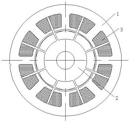
[0034] like Figure 6 to Figure 8 Show, the monoclon permanent magnetic non -brush -free DC motor of the auxiliary tooth and auxiliary winding of the present invention, including the stator and permanent magnet rotor 21; the maximum number of permanent magnet rotor is 2P;

[0035] The stator has multiple main polar teeth 15 and the stator auxiliary polar teeth 16, the main polar teeth 15 and the stator auxiliary polar teeth are settings;

[0036] Total altitude number of the main polar tooth 15 and the stator auxiliary polar teeth 16 is twice the number of motor permanent magnet rotor, that is, Z = 2 × 2P, P is extremely pair;

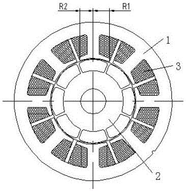
[0037] The width of the main polar teeth 15 is 1.55 to 2 times the width of the stator auxiliary polar teeth 16;

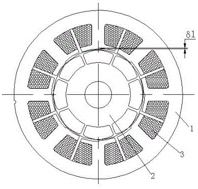
[0038] like Figure 8 Show, the stator main polar teeth 15 and the stator auxiliary polar teeth 16 are more width of the tooth width of the tooth of the stator in the statorThe ratio is 1 ~ 1.2;

[0039] The root of the main tooth 15 of the stat...


PUM


Abstract

The invention discloses a single-phase permanent magnet brushless direct-current motor with auxiliary teeth and auxiliary windings. The single-phase permanent magnet brushless direct-current motor includes a stator and a permanent magnet rotor; the stator is provided with a plurality of stator main pole teeth and stator auxiliary pole teeth which are uniformly distributed along the circumference of the stator, wherein the stator main pole teeth and the stator auxiliary pole teeth are arranged at intervals; the total number of the tooth slots of the stator main pole teeth and stator auxiliary pole teeth is twice of the number of the poles of the permanent magnet rotor of the motor; the width of the stator main pole teeth is 1.55 to 2 times of the width of the stator auxiliary pole teeth; main tooth arc surfaces are formed at the roots of the stator main pole teeth; auxiliary tooth arc surfaces are formed at the roots of the stator auxiliary pole teeth; slot openings are formed between the main tooth arc surfaces of the stator main pole teeth and the auxiliary tooth arc surfaces of the stator auxiliary pole teeth; and the central line of each slot opening deviates from the central line of a corresponding stator auxiliary pole tooth by a certain angle. After the single-phase permanent magnet brushless direct-current motor of the invention is energized, a magnetomotive force F generated by stator current has voltage difference, and therefore, a dead point can be eliminated; and the starting instant magnetomotive force voltage difference can change with the magnitude of the controllable stator current, and therefore, the starting instant magnetomotive force voltage difference can be controlled, and the motor can be started smoothly without vibration.

Description

Technical field [0001] The invention involves a motor, which specifically involves a single -phase permanent magnetic brush -free DC motor with auxiliary teeth and auxiliary winding. Background technique [0002] A single -phase permanent brushless DC motor In the half -phase conversion cycle, when the phase angle between the stator magnetic motility and the rotor magnetic flux is 0 and 180 degrees, the electromagnetic torque is 0.These two positions are "dead points". At this time, the motor cannot be started. Because the single -winding current is pulse waveform, the motor generates a large torque fluctuation, and the motor is manifested as a high vibration and high noise. [0003] For this, use Figure 1 to Figure 4 The four asymmetric air gap structures shown are obtained by the asymmetric magnetic resistance torque. It produces a targeted torque with permanent magnet torque synthesis."".To start normally, a large current of artificially gives a large current, showing that the...

Claims


Application Information

Patent Timeline
Patent Type & Authority Applications(China)
IPC IPC(8): H02K21/14H02K29/03
Inventor 章启忠张唯
Owner ZHE JIANG YILIDA VENTILATOR CO LTD
Why Eureka
Try Eureka