Layered two-dimensional projection generation and display

A technology of two-dimensional projection and image projection, applied in the field of diagnostic imaging, which can solve the problem of not allowing two or more types of tissue visualization at the same time, and achieve the effect of high spatial and contrast resolution

Active Publication Date: 2015-11-25
KONINKLJIJKE PHILIPS NV
View PDF1 Cites 5 Cited by
  • Summary
  • Abstract
  • Description
  • Claims
  • Application Information

AI Technical Summary

Problems solved by technology

Because each pixel in these images contains contributions from all tissue types blended together into a single number, none of the previous methods allow simultaneous visualization of two or more types of tissue

Method used


Image

  • Layered two-dimensional projection generation and display
  • Layered two-dimensional projection generation and display
  • Layered two-dimensional projection generation and display

Examples


Embodiment 200

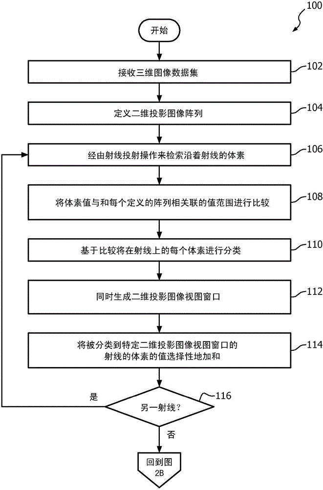
[0042] now refer to Figure 3A , receive 202 a three-dimensional dataset 68 or a dataset larger than three dimensions from any scanning modality such as SPECT, CT, PET, MR, and the like. The received data set 68 is used to specify and create 204 a three-dimensional data subset. Projection planes are then defined 206 corresponding to a selected number of planes, eg, the number of planes corresponds to different tissues, different organs, different structures (body, mechanics, electronics, geology, etc.). There is no limit on the number of projection planes that can be specified and calculated.

[0043] The position of the source 70, the position of the central axis and the corresponding position of the projection plane are then defined 208 . A two-dimensional data array of pixels for each projection plane is then defined 210 . For each projection plane, a 212 voxel value selection (mask) function is specified and defined as discussed below. Similarly, for each of the projec...


PUM


Abstract

An imaging system (10) generates a layered reconstructed radiograph (LRR) (66) of a subject. The system (10) takes as input a three-dimensional (3D) or higher dimensional data set (68) of the object, e.g. data produced by an image scanner (12). At least one processor (32) is programmed to define a set of two-dimensional (2D) projection images and associated view windows (60, 62, 64) corresponding to a set of voxel value (tissue) types with corresponding voxel value specification (50); determine the contribution of each processed voxel along each of a plurality of rays (72) through the 3D data set (68) to one of the predetermined voxel value (tissue) types in accordance with each voxel value with respect to the voxel value selection specification (50); and concurrently generate a 2D projection image corresponding to each of the voxel value specifications and related image view windows (60, 62, 64) based on the processed voxel values satisfying the corresponding voxel value specification (50). Each image is colorized differently and corresponding pixels in the images are aligned. An LRR (66) is generated by layering the aligned, colorized images and displaying as a multi-channel color image, e.g. an RGB image.

Description

technical field [0001] This application relates generally to diagnostic imaging. It specifically incorporates spatial relationships in medical image datasets generated by computed tomography (CT) systems, magnetic resonance (MR) imaging systems, positron emission tomography (PET) systems, single photon emission computed tomography (SPECT) A quick visualization of , is applied and will be described with specific reference to it. However, it should be understood that the present application is also applicable to other usage scenarios and is not necessarily limited to the above-mentioned applications. Background technique [0002] A planar radiographic image is a projection of a radiation source delivered through a three-dimensional object. The projection is created by connecting a line (ray) from the radiation source to a point on a plane on the opposite side of the target. Each point in the planar image is the sum of contributions from the target's small volume elements in...

Claims


Application Information

Patent Timeline
Patent Type & Authority Applications(China)
IPC IPC(8): G06T11/00G06T15/08
CPCG06T11/008G06T15/08G06T2207/10124G06T2207/10028G06T2207/10072G06T2207/30004
Inventor S·弗里戈
Owner KONINKLJIJKE PHILIPS NV
Why Eureka
Try Eureka