Interference performance clamping plate type cascading test device and method for smoke screen

A testing device and splint-type technology, which is applied in the direction of measuring device, scattering characteristic measurement, material analysis by optical means, etc. Uniform dispersion, etc.

Active Publication Date: 2015-12-02
中国人民解放军防化学院
View PDF5 Cites 2 Cited by
  • Summary
  • Abstract
  • Description
  • Claims
  • Application Information

AI Technical Summary

Problems solved by technology

However, the smoke screen materials used to interfere with infrared and millimeter waves usually have the characteristics of large particles and are not easy to disperse ev...

Method used


Image

  • Interference performance clamping plate type cascading test device and method for smoke screen
  • Interference performance clamping plate type cascading test device and method for smoke screen
  • Interference performance clamping plate type cascading test device and method for smoke screen

Examples


Embodiment 1

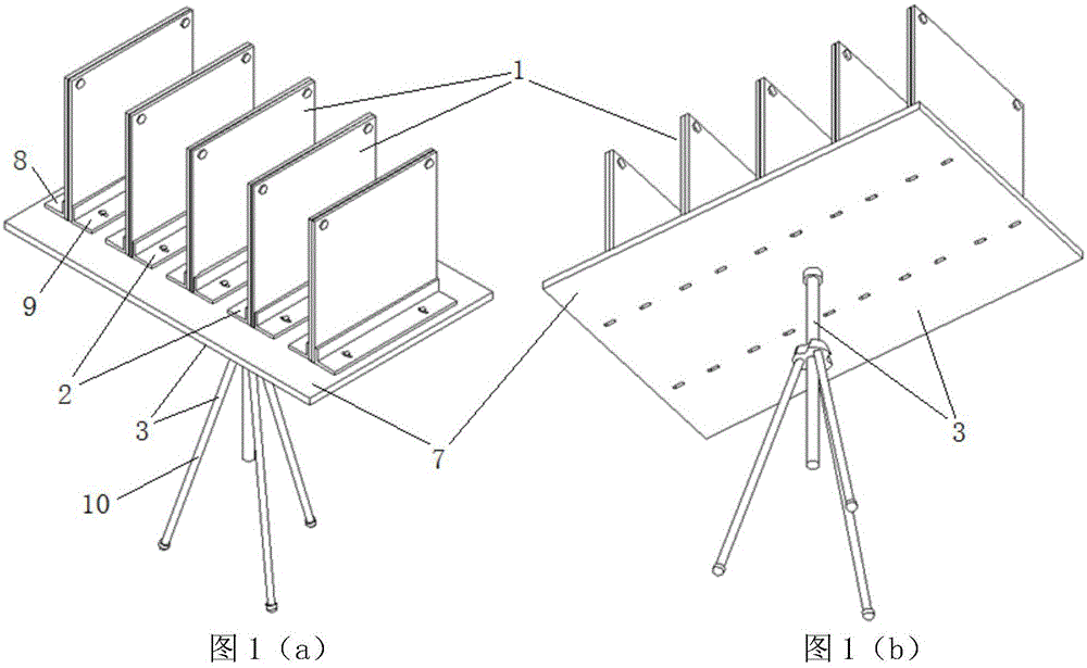
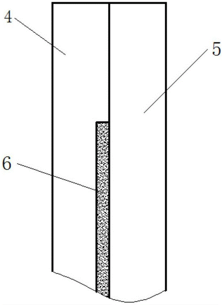
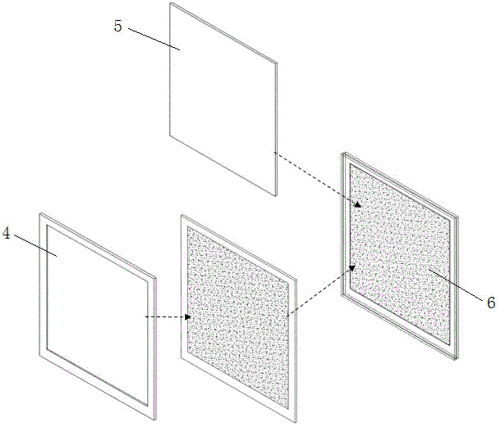
[0044]Test material 6 is a smoke screen material that interferes with the laser. The number 1-5 plywood group with shallower cavity depth should be selected. The finer the material particles, the smaller the number of the plywood group should be selected. After the test material is evenly loaded, each part of the test device is assembled in turn, supported on the ground and adjusted firmly. refer to Figure 9 A laser signal transmitter 11 is set up on one side, and a laser power detector 12 is set up on the other side to ensure that the connection between the laser signal transmitter and the center of the signal receiver effectively passes through the area where the test material in the sample splint group is located. When the laser signal emitted by the transmitter 11 passes through the splint set 1 , its intensity will be attenuated by the test material 6 , and the change of its intensity can be quantitatively measured through the receiver 12 on the other side. Comparing th...

Embodiment 2

[0046] Test material 6 is a powder anti-infrared material. The number 1-5 plywood group with shallower cavity depth should be selected. The finer the material particles, the smaller the label of the plywood group should be selected. After the test material is evenly loaded, each part of the test device is assembled in turn, supported on the ground and adjusted firmly. refer to Figure 9 , set up a black body or infrared signal transmitter 11 on one side, and set up an infrared spectroradiometer or other infrared receiver 12 on the other side to ensure that the connection between the infrared signal transmitter and the center of the signal receiver passes through the test material in the sample splint group effectively your region. When the infrared signal emitted by the transmitter 11 passes through the splint set 1 , its intensity will be attenuated by the test material 6 , and the change of its intensity can be quantitatively measured through the receiver 12 on the other si...

Embodiment 3

[0048] Test material 6 is a material that interferes with millimeter-wave smoke screens. The number 6-10 plywood set with a deeper inner cavity should be selected. The larger the material particles, the larger the number of the plywood set should be selected. After the test material is evenly loaded, each part of the test device is assembled in turn, supported on the ground and adjusted firmly. refer to Figure 9 A millimeter wave signal transmitter 11 is erected on one side, and a millimeter wave signal receiver 12 is erected on the other side to ensure that the connection between the millimeter wave signal transmitter and the center of the signal receiver effectively passes through the area where the test material in the sample splint group is located. When the millimeter wave signal emitted by the transmitter 11 passes through the splint set 1 , its intensity will be attenuated by the test material 6 , and the change of its intensity can be quantitatively measured through t...


PUM


Abstract

An interference performance clamping plate type cascading test device for a smoke screen comprises clamping plate sets, fixing rack sets and supporting plate sets. The clamping plate sets are vertically arranged and fastened by the fixing rack sets in a front-back mode, and the clamping plate sets and the fixing rack sets are installed on the supporting plate sets. Each fixing rack set is in a right-angle long strip shape, and one side of each fixing rack set is provided with a trapezoid annular hole. Sample clamping plat sets with different thicknesses are fixed conveniently through screws. After being detached into the clamping plate sets, the fixing rack sets and the supporting plate sets at ordinary times, the testing device is convenient to carry to a test field. A test method includes the steps that after the test device is assembled, a photoelectric signal emitter is erected on one side frame, and a receiver is erected on the other side frame; when infrared, millimeter-wave and electromagnetic signals emitted by the emitter penetrate the clamping plate sets on the same layer or multiple layers, the receiver on the other side face can measure the change of intensity of the signals quantitatively; the change, generated before and after the signals penetrate a tested sample plate, of the intensity of the infrared, millimeter-wave and the electromagnetic signals emitted by the emitter are compared, and interference performance of a smoke screen material can be assessed quantitatively.

Description

【Technical field】 [0001] The invention relates to a splint-type lamination test device and method for the interference performance of smoke screen materials, which are mainly used for testing the interference performance of smoke screen materials to infrared, millimeter wave and other electromagnetic signals. It belongs to the technical field of passive interference photoelectric countermeasures. 【Background technique】 [0002] In the passive interference photoelectric countermeasure technology, it is an important means to select smoke screen materials or evaluate smoke screen interference performance to test the performance of various smoke screens to interfere with infrared, millimeter wave and other electromagnetic waves through evaluation tests. However, the smoke screen materials used to interfere with infrared and millimeter waves usually have the characteristics of large particles and are not easy to disperse evenly. The difficulty of testing such tests increases and...

Claims


Application Information

Patent Timeline
IPC IPC(8): G01N21/01G01N21/47G01N21/3563
Inventor 王玄玉白海涛王颖辉庞敏晖刘志龙
Owner 中国人民解放军防化学院
Why Eureka
Try Eureka