A driving circuit and driving method for a permanent magnet synchronous motor

A permanent magnet synchronous motor and drive circuit technology, applied in electronic commutation motor control, single motor speed/torque control, electrical components and other directions, can solve the problems of complex algorithm and large amount of calculation, and achieve simple algorithm and motor efficiency. High, easy to achieve results

Active Publication Date: 2018-06-26
SILERGY SEMICON TECH (HANGZHOU) CO LTD
View PDF10 Cites 1 Cited by
  • Summary
  • Abstract
  • Description
  • Claims
  • Application Information

AI Technical Summary

Problems solved by technology

The traditional control scheme of permanent magnet synchronous motor without position sensor adopts vector control, and the vector control without position sensor can realize better control of permanent magnet synchronous motor, but there are complex algorithms and large amount of calculation, which requires a higher-level processor

Method used


Image

  • A driving circuit and driving method for a permanent magnet synchronous motor
  • A driving circuit and driving method for a permanent magnet synchronous motor
  • A driving circuit and driving method for a permanent magnet synchronous motor

Examples


Embodiment Construction

[0036] Several preferred embodiments of the present invention will be described in detail below with reference to the accompanying drawings, but the present invention is not limited to these embodiments. The present invention covers any alternatives, modifications, equivalent methods and schemes made on the spirit and scope of the present invention. In order to provide the public with a thorough understanding of the present invention, specific details are set forth in the following preferred embodiments of the present invention, but those skilled in the art can fully understand the present invention without the description of these details.

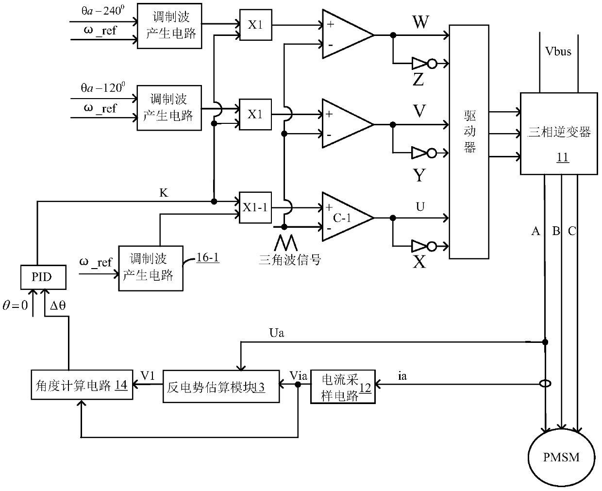
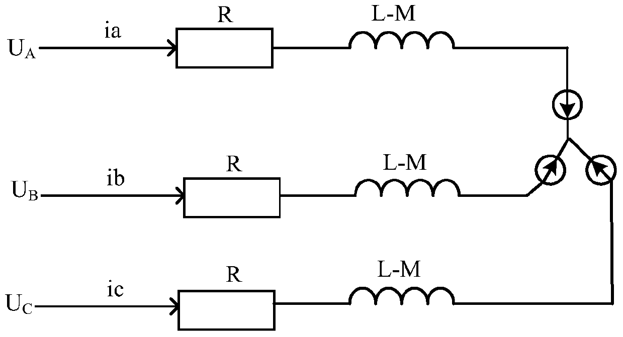
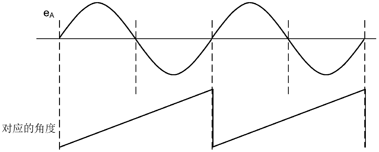
[0037] refer to figure 1 , is shown as the circuit block diagram of the first embodiment of the drive circuit of the permanent magnet synchronous motor according to the present invention; the three-phase inverter 11 receives the external voltage signal V bus , to be converted into a three-phase alternating voltage signal to supply a perm...


PUM


Abstract

The invention discloses a driving circuit and a driving method of a permanent magnet synchronous motor. By sampling the voltage and current information of one phase of the permanent magnet synchronous motor, the back EMF information of the corresponding phase is estimated, and then the back EMF information will be characterized The angle difference between the first voltage signal of the information and the current sampling signal representing the current information is calculated to obtain an angle difference signal, and the angle difference signal is used to adjust the amplitude of the first horseshoe-shaped modulation wave to control the rotation of the rotor The phase of the current coincides with that of the first horseshoe-shaped modulation wave, so that the torque produced per ampere of current is maximized. The invention obtains the counter electromotive force information through estimation, does not need complex coordinate transformation, and has simple algorithm and easy realization. In addition, the present invention changes the phase difference between the back electromotive force of the motor and the phase current by adjusting the current of the motor, so as to realize maximum torque control, and the efficiency of the motor is high.

Description

technical field [0001] The invention relates to the technical field of motor control, and more specifically, relates to a driving circuit and a driving method of a permanent magnet synchronous motor. Background technique [0002] Permanent magnet synchronous motor (PMSM) has played an important role in daily life, industrial and agricultural production, and national economic development due to its own advantages such as light weight, small size, simple structure, and high power density. Due to the continuous improvement and improvement of the performance of permanent magnet materials and the further development of power electronic devices, the application of permanent magnet synchronous motors is becoming more and more extensive. In some applications, it is hoped to control the cost of the system to the maximum extent. The sensorless technology eliminates conventional position sensors, such as photoelectric encoder discs, resolvers and other equipment, which greatly reduces ...

Claims


Application Information

Patent Timeline
Patent Type & Authority Patents(China)
IPC IPC(8): H02P6/18H02P6/08
CPCH02P6/157H02P6/182H02P23/0004H02P23/0009
Inventor 黄晓冬张幸浩
Owner SILERGY SEMICON TECH (HANGZHOU) CO LTD
Why Eureka
Try Eureka