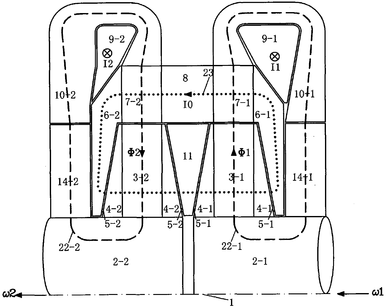
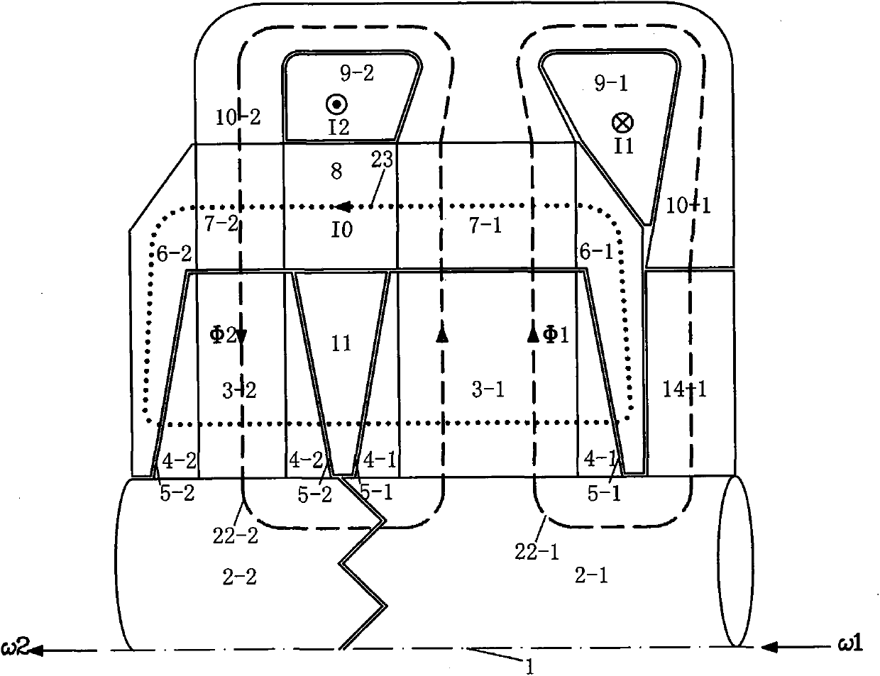
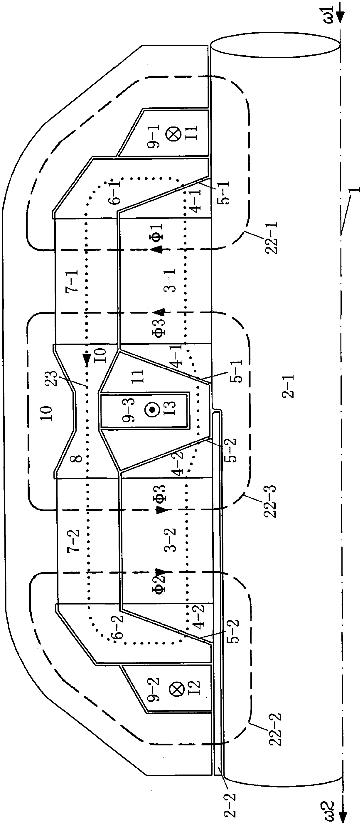
Wind power system with flywheel and unipolar DC electromagnetic drive

A technology of wind power generation system and transmission, which is applied in the direction of wind power generators, wind power generation, electromechanical devices, etc. that store kinetic energy, and can solve the problems of wind power generation system power generation instability, small volume density, heat generation and wear damage of protective bearings, etc.

Active Publication Date: 2019-07-30
徐立民
View PDF3 Cites 0 Cited by
  • Summary
  • Abstract
  • Description
  • Claims
  • Application Information

AI Technical Summary

Problems solved by technology

However, from the overall perspective of the power grid, there are still the following problems in terms of comprehensive indicators: due to the great instability and randomness of the wind speed, the wind power obtained by the wind wheel is always fluctuating in a large range, and there is no energy storage The power generation of the installed wind power generation system is very unstable, and the installed capacity of wind turbines is generally not regarded as a stable and reliable power generation capacity in the power grid. , due to the instability and unplanned nature of wind power generation, it is very difficult for the grid to accommodate wind power, and it is necessary to increase sufficient peak-shaving supporting facilities, including peak-shaving emergency generator sets, pumped storage power stations, etc.; wind power instability is also Decrease the power quality and increase the instability of the power grid; in addition, in order to fully absorb the wind energy under all wind conditions, the rated capacity of the wind power system is designed to be very large, and the design / rated wind speed corresponding to the rated power is much higher than the annual wind speed. The average wind speed and the annual average power only account for about 19% of the rated power, and the effective utilization rate of the equipment capacity is very low
[0013] (1) Since a single wheel body mass can only be made into a cylindrical ring with a thinner radial thickness, the practical energy storage volume density is relatively small
[0014] (2) The rotation imbalance of the existing energy storage flywheel is large, the process is difficult to solve, and it is easy to cause large unbalanced vibrations, and the unbalance will be aggravated as the use time increases
[0015] (3) The problems caused by the use of magnetic bearings for radial load bearings and axial load bearings: the active control system of magnetic suspension bearings that must have high reliability is added. Compared with mechanical bearings or permanent magnetic bearings that do not need to be controlled, After all, the magnetic suspension bearing and its control system are a complex system, and the probability of problems is high. Once a failure occurs, because the inertial rotation of the flywheel cannot be stopped in a short time, the heat and wear of the protective bearing will be very serious and damage it. Causing vicious damage to the flywheel rotor system
[0016] (4) The high-frequency and high-speed motor has a large calorific value and limited heat conduction, which limits the increase in motor power.
The total efficiency of variable frequency motor + frequency converter is also low, that is, the efficiency of this energy transfer method is low

Method used


Image

  • Wind power system with flywheel and unipolar DC electromagnetic drive
  • Wind power system with flywheel and unipolar DC electromagnetic drive
  • Wind power system with flywheel and unipolar DC electromagnetic drive

Examples


Embodiment Construction

[0266] A 1.5MW wind power system with flywheel and HET ( Figure 21 The specific implementation of) is as follows.

[0267] The system includes: a horizontal-axis variable-pitch blade wind turbine, a horizontal speed-increasing gear box connected to the wind wheel shaft, and a unipolar DC electromagnetic drive (HETw) connected to the output shaft of the gear box and indirectly connected to the generator shaft. A horizontal synchronous generator, a suspended flexible flywheel device, a unipolar DC electromagnetic drive (HETf) connecting the flywheel shaft and the generator shaft, a mechanical brake device at the wind wheel shaft, and a yaw drive active pair The wind mechanism, a nacelle, a tower, and control and accessory systems.

[0268] The wind wheel uses three airfoil profile blades. The maximum value of the wind energy utilization coefficient Cp is 0.47, and the corresponding best tip speed ratio is 7. The rated design point uses this best tip speed ratio and the maximum Cp va...


PUM


Abstract

The invention relates to a wind power generation system. According to the wind power generation system, flywheels are taken as energy storage devices, a one-pole dc magnetic driver (HET) is taken as flywheel energy transmission equipment, the stable power generation function is realized, and energy transmission advantages of the HET perform; a vertical flexible flywheel and a suspension type flexible flywheel are further employed, problems of a large-mass flywheel and a bearing are solved. HET speed change transmission is employed between the flywheel and a generator to greatly improve wind energy capture efficiency. Three schemes for energy transmission among a wind wheel, the generator and the flywheel, the first scheme is a no-HET scheme between the wind wheel and the generator, namely, an energy storage device and energy transmission equipment thereof are added to a routine wind power system in the prior art, the second scheme is an independent HET scheme between the wind wheel and the generator, the third scheme is a scheme through which the wind wheel, the generator and the flywheel are respectively connected with one HET half matching part.

Description

[0001] Technical field [0002] The invention relates to a wind power generation system, particularly a wind power generation system with an energy storage device. Background technique [0003] Wind power is recognized as a green energy source with broad prospects. At present, the technology has been successfully applied for a long time, and the economic competitiveness of the wind power system itself is constantly improving. However, from the overall perspective of the power grid, in terms of comprehensive indicators, there are still the following problems: Due to the large instability and randomness of wind speed, the wind energy power obtained by the wind turbine is always variable in a large range, and there is no energy storage. The power generation of the installed wind power generation system is very unstable. Generally, the installed capacity of wind turbines is not regarded as a stable and reliable power generation capacity in the grid. The increase in installed capacity o...

Claims


Application Information

Patent Timeline
Patent Type & Authority Patents(China)
IPC IPC(8): H02J3/30H02J3/38H02K16/02F03D9/12
CPCY02E10/72Y02E10/76Y02E60/16Y02E70/30
Inventor 徐立民
Owner 徐立民
Why Eureka
Try Eureka