
A Gain Boosted Operational Transconductance Amplifier

A technology of transconductance amplifiers and MOS tubes, which is applied in DC-coupled DC amplifiers, differential amplifiers, and improved amplifiers to reduce temperature/power supply voltage changes. Issues such as little improvement

Inactive Publication Date: 2017-12-22
GUANGXI NORMAL UNIV
View PDF3 Cites 0 Cited by
  • Summary
  • Abstract
  • Description
  • Claims
  • Application Information

AI Technical Summary

Problems solved by technology

Although the current multiplexing technology improves the utilization rate of the current in the circuit, this solution increases the transconductance by sacrificing the phase margin of the circuit, and the gain improvement is not large. Under the existing deep submicron process, RFC The gain of the operational amplifier is far from the accuracy required in practice, and it is difficult to be widely used

Method used


Image

  • A Gain Boosted Operational Transconductance Amplifier
  • A Gain Boosted Operational Transconductance Amplifier
  • A Gain Boosted Operational Transconductance Amplifier

Examples


Embodiment Construction

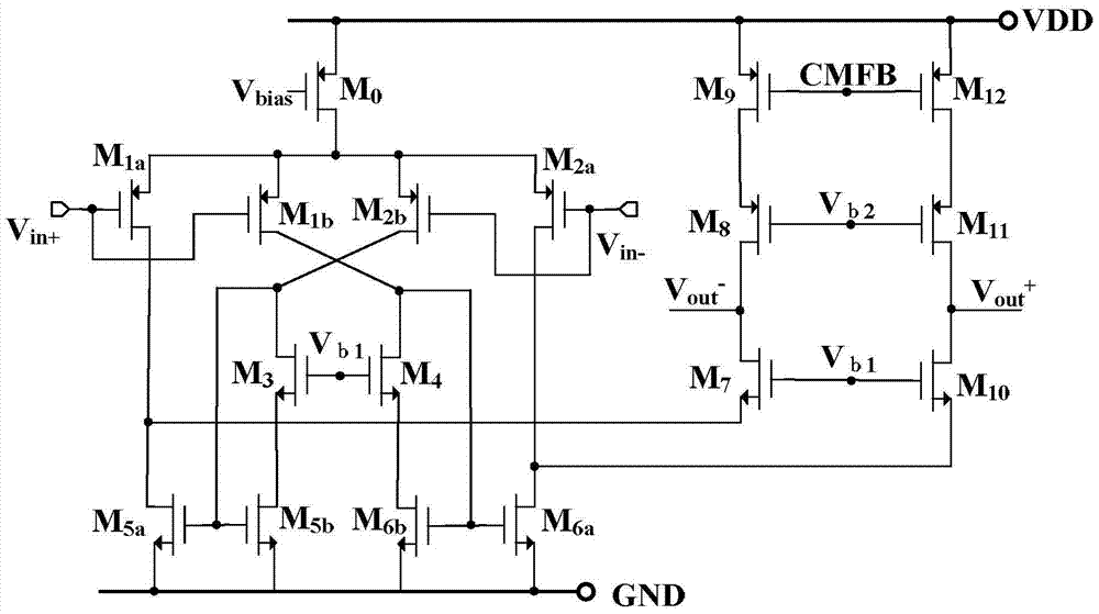
[0028] The traditional multiplexing folded cascode operational amplifier, that is, the RFC operational amplifier is used as a comparison example, and its circuit structure is as follows figure 1 shown. It includes a bias constant current source and its sequentially connected differential input, load current mirror and cascode output stage.

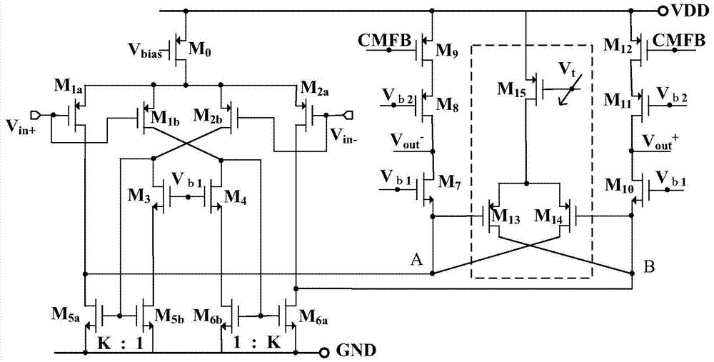
[0029] This gain-boosted operational transconductance amplifier implementation is for example figure 2 As shown in , the bias constant current source is sequentially connected in series with the differential input, the load current mirror, the cascode output stage and the adjustable auxiliary differential pair. The bias constant current source is a P-type MOS tube M 0 , whose source is connected to the power supply VDD,M 0 The gate is connected to the bias voltage V bias ; Differential input consists of 4 P-type MOS transistors M 1a , M 2a , M 1b and M 2b The load current mirror consists of 6 N-type MOS transistors M 3 , M 4 , M...


PUM


Abstract

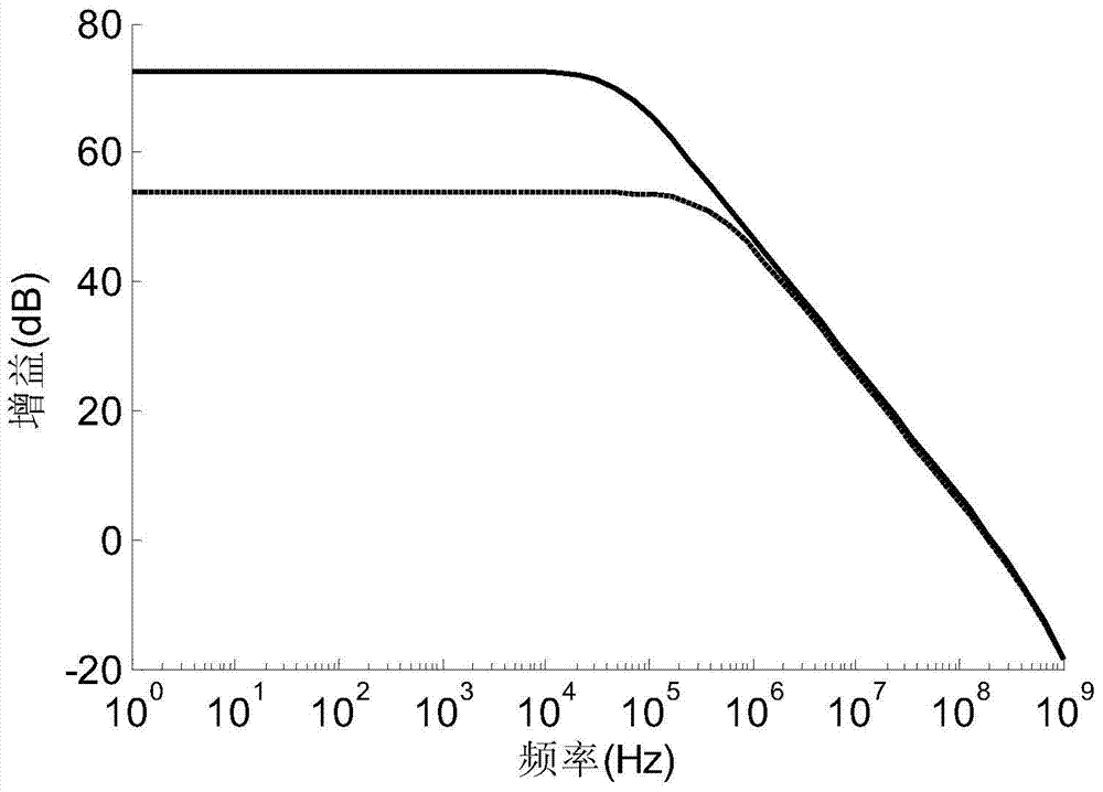
The invention discloses a gain increased operational transconductance amplifier which is formed in a manner that a bias constant current source is sequentially connected with differential input, a load current mirror, a cascode output stage and an adjustable auxiliary differential pair in sequence, wherein the differential input is composed of four PMOS pipes namely M1a, M2a, M1b and M2b; the load current mirror is composed of six NMOS pipes namely M3, M4, M5a, M6a, M5b and M6b; the cascode output stage is composed of six MOS pipes namely M7, M8, M9, M10, M11 and M12; the adjustable auxiliary differential pair is composed of M13, M14 and M15. Reutilization of current and the output stage increased adjustable auxiliary differential pair thoroughly solve the inherent contradiction among gain, bandwidth, power dissipation and the like in a circuit; the gain increased operational transconductance amplifier is slightly influenced by output voltage, an additional pole is not introduced, the simulation results show same static power dissipation, and multiplication is realized for gain and bandwidth; the gain increased operational transconductance amplifier further has the characteristics of fine tuning and high accuracy and is applicable to communication, electronic measurement and automatic control systems.

Description

technical field [0001] The invention relates to an operational amplifier, in particular to an operational transconductance amplifier with increased gain. Background technique [0002] Operational amplifiers have been widely used in analog circuits such as power supplies, analog-to-digital converters, and filters. With the decrease of power supply voltage and the further reduction of process size, the channel length of transistors is continuously reduced, resulting in the decrease of intrinsic gain of transistors. Under such conditions, the design of high-gain op amps faces great challenges. In the prior art, two or three stages of cascading are used. In this manner, each cascading brings high gain and at the same time introduces a low-frequency pole, resulting in negative phase shift and degraded phase margin. In order to maintain the stability of the system, the principle of Miller compensation is generally used. This kind of pole separation compensation will seriously deg...

Claims


Application Information

Patent Timeline
Patent Type & Authority Patents(China)
IPC IPC(8): H03F1/30H03F3/45
Inventor 宋树祥凡东东蒋品群程远垚
Owner GUANGXI NORMAL UNIV
Learn More