Low-emission combustion chamber with double-layer axial hydrocyclone adopted at precombustion stage

A technology of pre-combustion stage and combustion chamber, which is applied in the direction of combustion chamber, continuous combustion chamber, combustion method, etc., can solve the problems of reinforcement, difficulty in balancing combustion efficiency and low emission, and poor fuel atomization, so as to reduce pollution emissions and effectively It is beneficial to control the temperature of the combustion zone and improve the combustion performance

Inactive Publication Date: 2015-12-16
BEIHANG UNIV
View PDF0 Cites 21 Cited by
  • Summary
  • Abstract
  • Description
  • Claims
  • Application Information

AI Technical Summary

Problems solved by technology

[0005] The technical problem to be solved by the present invention is: aiming at the problem that the fuel atomization of the existing low-emission combustor is poor in small working conditions, and the combustion efficiency and low emission are difficult to balance, the staged combustion mode is adopted, and the main combustion stage adopts premixed combustion , the pre-combustion stage adopts a double-layer axial swirler to strengthen the atomization and mixing of fuel under small working conditions, so as to ensure stable combustion, improve the combustion performance of the combustion chamber under small working conditions, and reduce pollution emission

Method used


Image

  • Low-emission combustion chamber with double-layer axial hydrocyclone adopted at precombustion stage
  • Low-emission combustion chamber with double-layer axial hydrocyclone adopted at precombustion stage
  • Low-emission combustion chamber with double-layer axial hydrocyclone adopted at precombustion stage

Examples


Embodiment Construction

[0025] The present invention will be further described below in conjunction with the accompanying drawings and specific embodiments.

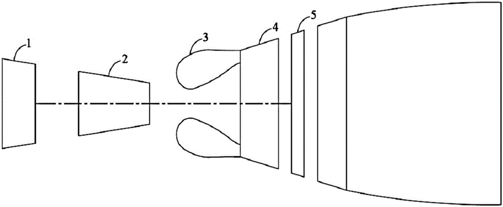
[0026] figure 1 It is a schematic diagram of the engine structure, including a low-pressure compressor 1, a high-pressure compressor 2, a combustion chamber 3, a high-pressure turbine 4 and a low-pressure turbine 5. When the engine is working, the air is compressed by the low-pressure compressor 1 and the high-pressure compressor 2 and then enters the combustion chamber 3. Fuel is injected and combusted to form high-temperature and high-pressure gas, which impacts the high-pressure turbine 4 and the low-pressure turbine 5, thereby driving the low-pressure compressor. 1 and high-pressure compressor 2 work, and output power.

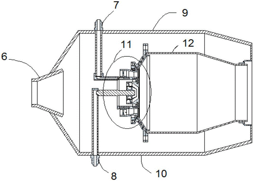
[0027] Such as figure 2As shown, a single-ring cavity structure is adopted, and the main structure includes a diffuser 6, a casing 9 outside the combustion chamber, a casing 10 inside the combustion chamber, a flame tube...


PUM


Abstract

The invention discloses a low-emission combustion chamber with a double-layer axial hydrocyclone at a precombustion stage. The combustion chamber is of a single annular cavity structure and structurally comprises a pressure expander, a combustion chamber exterior casing, a combustion chamber interior casing, a flame tube and a combustion chamber head; all combustion-used air enters the flame tube through the combustion chamber head, a staged combustion scheme is adopted, and the combustion is divided into into the precombustion stage and a primary combustion stage; a premixed combustion mode is adopted at the primary combustion stage, and a diffusive combustion mode serves as the main mode of the precombustion stage; the double-layer axial hydrocyclone is adopted at the precombustion stage, two blasts of rotational flow can maintain individual flowing through a partition plate, and momentum loss due to the fact that the two blasts of rotational flow make contact with each other too early is avoided; the two blasts of rotational flow are utilized for reinforcing fuel oil atomization and mixing, meanwhile, reasonable recirculating zone distribution is generated, efficient and stable combustion under small working conditions is guaranteed, and meanwhile pollutant emission is lowered; the combustion chamber is simple in structure at the precombustion stage and easy to machine and install, combustion chamber emission under small working conditions can be lowered, and thereby the low emission performance of a total landing and taking-off cycle of the combustion chamber is improved.

Description

technical field [0001] The invention relates to a low-emission combustion chamber, in particular to a low-emission combustion chamber in which a pre-combustion stage adopts double-layer axial swirlers. Background technique [0002] An aero engine is a highly complex and sophisticated thermomechanical engine that provides the power required for aircraft to fly. As the heart of the aircraft, it is known as the "Flower of Industry", which directly affects the performance, reliability and economy of the aircraft. Aeroengines can be simply classified into civil aeroengines and military aeroengines according to their usage. Compared with military aeroengines, civil aeroengines have stricter requirements in terms of low fuel consumption, low emissions, and low noise. Among them, low emissions mainly need to be achieved by optimizing the design of the combustion chamber. [0003] The main pollutant emissions of modern civil aviation engines include: nitrogen oxides (NOx), carbon ...

Claims


Application Information

Patent Timeline
Patent Type & Authority Applications(China)
IPC IPC(8): F23R3/30F23R3/38F23R3/58
Inventor 林宇震韩啸张弛王波
Owner BEIHANG UNIV
Why Eureka
Try Eureka