Accurate efficient adjusting device for machine tool assembly
A kind of machine tool and high-efficiency technology, applied in the direction of adopting mechanical devices, mechanical measuring devices, measuring devices, etc., can solve the problems that affect the life of the screw and bearing, the transmission accuracy cannot meet the production requirements, and the composition and assembly structure are complicated, etc., to achieve Improve debugging accuracy, avoid abnormal wear and damage, and design reasonable effects
Inactive Publication Date: 2015-12-16
KUNSHAN ALLOUT PRECISION MACHINERY
View PDF5 Cites 0 Cited by
- Summary
- Abstract
- Description
- Claims
- Application Information
AI Technical Summary
Problems solved by technology
[0003] Traditional CNC machine tools are usually composed of main engine, numerical control device, driving device, auxiliary device and other components, and its composition and assembly structure are relatively complicated. Various cutting mechanical parts, the driving device includes the spindle drive unit, the feed unit, the spindle motor and the feed motor, etc., which realize the spindle and feed drive through the electric or electro-hydraulic servo system under the control of the numerical control device. When the two feeds are linked together, the processing of positioning, straight lines, plane curves and space curves can be completed. In order to ensure the accuracy and high efficiency of machine tool production operations, the feed mechanism of the host machine and the feed unit of the drive device, spindle motor and Feed motors, etc., need to be installed stably and accurately on the bearing housing, motor housing and nut housing of the machine body. In the traditional installation process, the screw is usually used as a jig to debug the bearing housing, motor housing, and nut housing, etc. However, due to the influence of gravity, screw length, clearance, etc., the three-point line of the screw is seriously out of tolerance, seriously affecting the life of the screw and the life of the bearing, resulting in transmission accuracy that cannot meet the production requirements, resulting in production Low product qualification rate, serious waste of raw materials, etc., which are currently urgently to be solved
Method used
View moreImage
Smart ImageViewing Examples

Examples
Embodiment
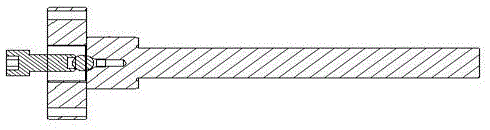
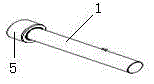
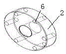
[0022] further as Figure 2 to Figure 6 As shown, firstly install the positioning snare 2 on the bearing seat to be installed of the drive part of the machine tool, then snap the first test rod 1 into the positioning snare 2, and then connect one end of the second test rod 3 to the first test rod 1 , one end of the positioning connecting column 7 is connected to the motor seat, and then the third test rod 4 is connected to the nut seat. Finally, the numerical information displayed by the centering lever table used in the test is relative to the bearing seat, the motor seat and the nut seat. Adjust the position.
Login to View More PUM
 Abstract
The invention belongs to the technical field of machine tool assembly and application and specifically discloses an accurate efficient adjusting device for machine tool assembly. The device includes a first testing rod, a positioning loop used in cooperation with the first testing rod, a second testing rod used in cooperation with the first testing rod and a third testing rod used in cooperation with the second testing rod. The adjusting device is reasonable in design, stable in working stability and convenientin control. Large nuts and steel balls are used in combination for locking the first testing rod, the second testing rod and the third testing rod, so that influence of gravity is overcome naturally and adjusting precision is improved. At the same time, by using the first testing rod, the second testing rod and the third testing rod for adjusting a bearing seat, a motor base, a nut base and the like, shortcomings of using a screw rod as a tool are overcome and mounting errors are limited within a normal allowable range. An out-of-tolerance problem of three points and one line of the screw rod is solved, abnormal abrasion and damage of the screw rod are avoided, so that the positioning precision and repeated positioning precision of the machine tool are improved and stabilized effectively.
Description
technical field [0001] The invention belongs to the technical field of mechanical assembly applications, and in particular relates to a precise and efficient debugging device for machine tool assembly, which can quickly perform three-point and one-line adjustments on bearing seats, motor seats, and nut seats. Background technique [0002] Machine tool (English name: machine tool) refers to a machine that manufactures a machine, also known as a machine tool or machine tool, and is customarily referred to as a machine tool. Generally divided into metal cutting machine tools, forging machine tools and woodworking machine tools. There are many ways to process mechanical parts in modern machinery manufacturing. In addition to cutting, there are casting, forging, welding, stamping, extrusion, etc., but for parts with high precision requirements and finer surface roughness requirements, they generally need to be processed. The cutting method is used on the machine tool for final p...
Claims
Login to View More Application Information
Patent Timeline
 Patent Type & Authority Applications(China)
IPC IPC(8): G01B5/00
Inventor 王志松
Owner KUNSHAN ALLOUT PRECISION MACHINERY