
Movable rainfall simulating and flow collecting device

A flow-collecting device and mobile technology, applied in the field of mobile rainfall simulation flow-collecting devices, can solve the problems of inability to set different slopes simply and accurately, destroy the ecological landscape, occupy a lot of land, etc. The effect of using and occupying a small area

Inactive Publication Date: 2015-12-16
INST OF WATER RESOURCES FOR PASTERAL AREA MINIST OF WATER RESOURCES P R C +1
View PDF7 Cites 12 Cited by
  • Summary
  • Abstract
  • Description
  • Claims
  • Application Information

AI Technical Summary

Problems solved by technology

However, generally a single-built fixed runoff plot cannot meet the experimental requirements, and the error is relatively large. For a fixed runoff plot, the slope is a single slope; runoff plot
Setting up multiple runoff plots not only occupies a lot of land, but also requires a large investment in construction. More importantly, the construction of runoff plots will damage the local ecological landscape and cause certain water and soil loss, which will bring many problems to the construction and experimental observation of runoff plots with different slopes. Inconvenient, especially under the condition of limited funds, the insufficient construction cost has become the limiting factor of the runoff plot test, so it is impossible to simply and accurately set different slopes to meet the needs of experimental simulation

Method used


Image

  • Movable rainfall simulating and flow collecting device
  • Movable rainfall simulating and flow collecting device
  • Movable rainfall simulating and flow collecting device

Examples


Embodiment Construction

[0044] The principles and features of the present invention are described below in conjunction with the accompanying drawings, and the examples given are only used to explain the present invention, and are not intended to limit the scope of the present invention.

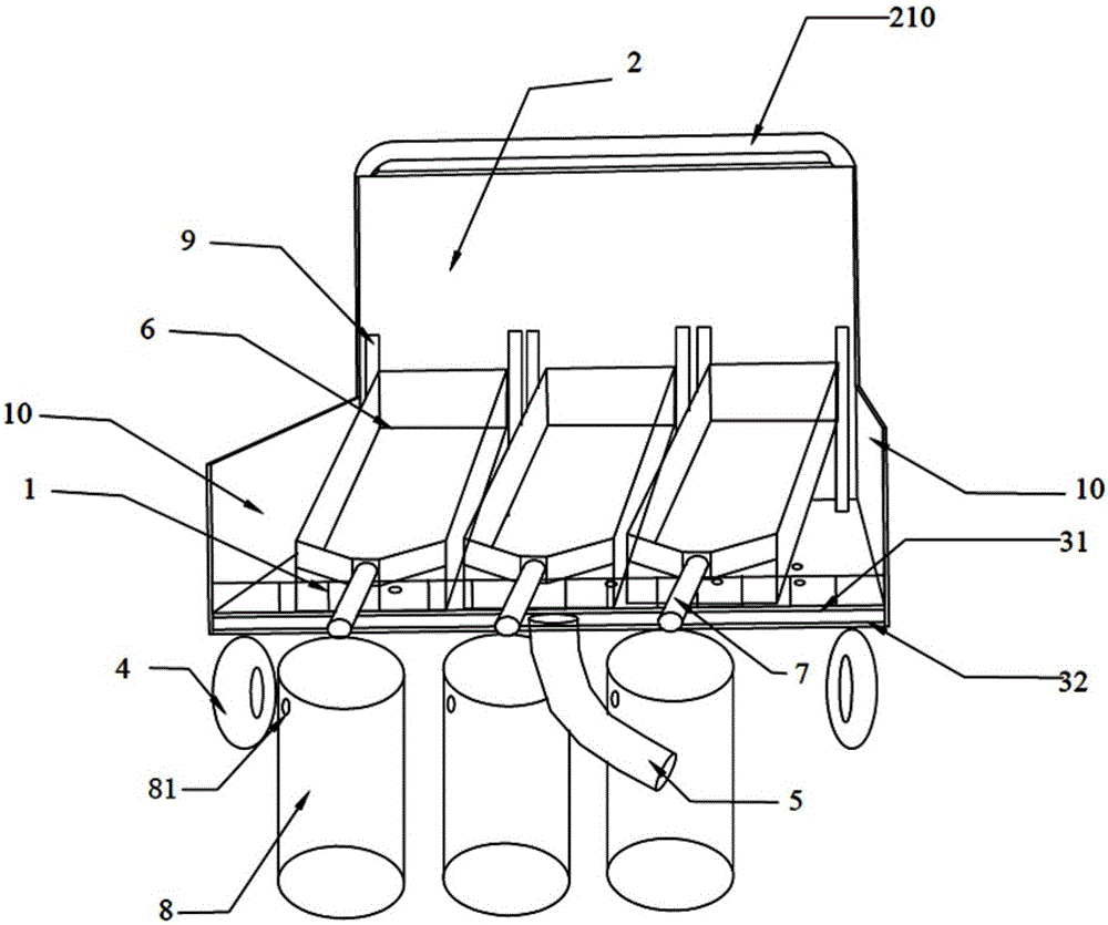
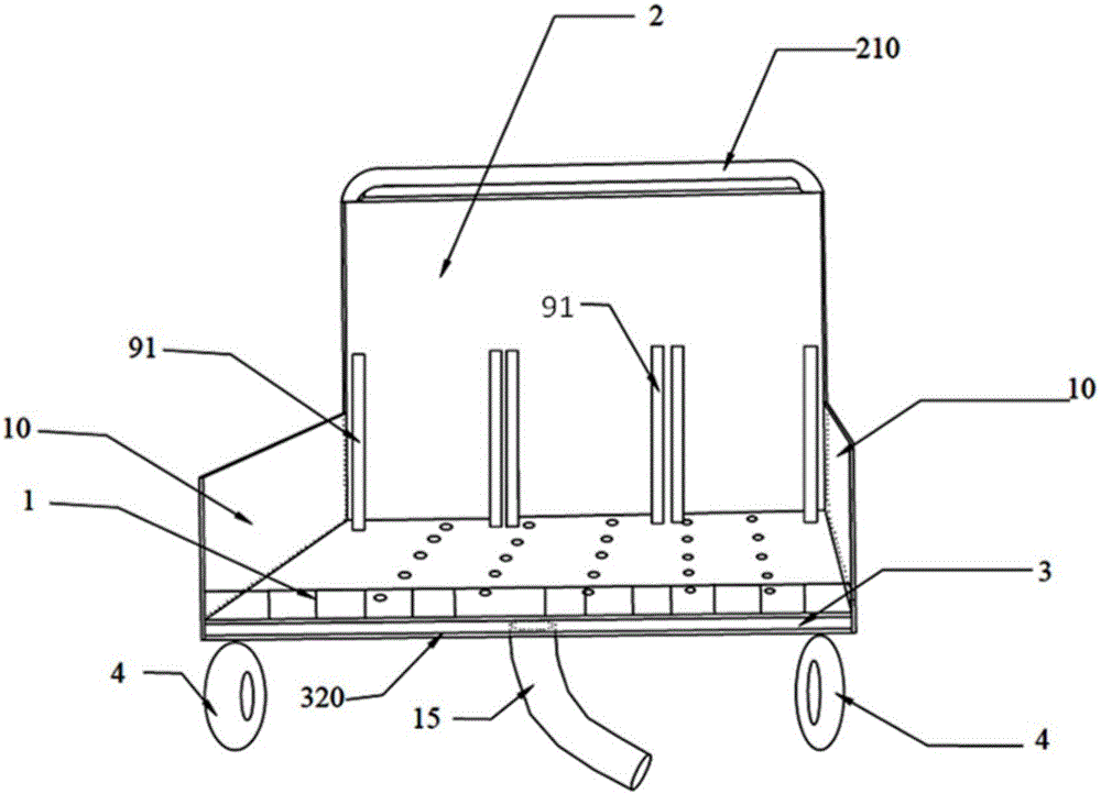
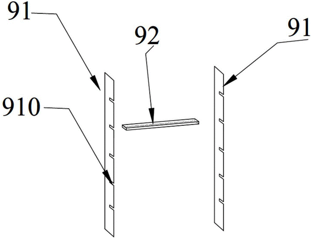
[0045] Such as Figure 1 to Figure 6 As shown, a mobile rainfall simulation collecting device includes a carrier vehicle with universal wheels 4 at the bottom, multiple sets of slope supports 9 , multiple runoff areas 6 , collecting buckets 8 , and diversion pipes 7 .

[0046] The truck includes a front wall 1, two side panels 10, a rear panel 2 and a bottom compartment 3 for collecting rainwater; type structure, the front wall 1 is a railing, the two side panels 10 and the rear panel 2 are all plate-shaped structures; the bottom compartment 3 is a double-layer structure, including an upper deck 31 and a lower deck 32, and the bottom compartment The upper plate 31 of 3 is a perforated plate, and the lower plate 32 ...


PUM

PropertyMeasurementUnit
thicknessaaaaaaaaaa

Abstract

The invention relates to a movable rainfall simulating and flow collecting device which comprises a bearing trolley, multiple slope position supports, multiple runoff plots, flow collecting barrels and flow guide pipes. Universal wheels are arranged at the bottom of the bearing trolley. The bearing trolley comprises a front wall, two side plates, a rear plate and a bottom compartment used for collecting rainwater. The bottom compartment is of a two-layer structure and comprises an upper plate and a lower plate. The upper plate of the bottom compartment is a porous plate. A rainwater outlet is formed in the lower plate of the bottom compartment and connected with a rainwater recovery pipe. The slope position supports are located on the upper plate of the bottom compartment. The rear ends of the runoff plots are located on the slope position supports. The front ends of the runoff plots abut against the front wall. Flow guide holes are formed in the front ends of the runoff plots and connected with one ends of the flow guide pipes. The other ends of the flow guide pipes extend out from the upper side of the front wall, and the flow collecting barrels are arranged below the other ends, extending out of the upper side of the front wall, of the flow guide pipes. The movable rainfall simulating and flow collecting device has the advantages of being light in weight, convenient to carry, resistant to corrosion and not prone to rusting, and moving fast.

Description

technical field [0001] The invention relates to a device for observing the process of runoff and sediment production under natural rainfall or simulated rainfall conditions, in particular to a mobile rainfall simulation flow collection device containing multiple groups of runoff plots. Background technique [0002] Runoff and sediment transport formed by rainfall is an important factor causing soil erosion and its harm. Rainfall can directly hit the soil, forming splash and intrusion candles, and rainfall to the surface forms surface runoff, scours the soil, and changes some internal characteristics of the soil. In order to study the impact of rainfall on land productivity and ecological environment, as well as the impact of different soil and water conservation measures on it, runoff plot observation is one of the important methods of soil and water conservation observation and experiment, and it is the main means to study and test runoff and sediment on a microscopic scale...

Claims


Application Information

Patent Timeline
Patent Type & Authority Applications(China)
IPC IPC(8): G01N33/24
Inventor 董智郭建英李红丽李锦荣田秀民陈新闯张光灿王合云
Owner INST OF WATER RESOURCES FOR PASTERAL AREA MINIST OF WATER RESOURCES P R C
Learn More