Air cathode and microbial fuel cell

An air cathode and fuel cell technology, applied in the fields of materials, energy, and environment, can solve problems to be improved, and achieve the effect of improving the use effect.

Active Publication Date: 2015-12-16
TSINGHUA UNIV
View PDF4 Cites 6 Cited by
  • Summary
  • Abstract
  • Description
  • Claims
  • Application Information

AI Technical Summary

Problems solved by technology

[0003] However, the catalytic efficiency and battery performance of air cathodes curr

Method used


Image

  • Air cathode and microbial fuel cell
  • Air cathode and microbial fuel cell
  • Air cathode and microbial fuel cell

Examples


Embodiment 1

[0076] Preparation of cathode catalyst: mixing and grinding sodium chloride and zinc chloride evenly, wherein the molar ratio of zinc chloride is 40-45%. Add 1 g of 1-ethyl-3-methylimidazolium dicyanamide per 13 g of sodium chloride and zinc chloride mixture. The mixture was heated in a muffle furnace to 1000°C at a ramp rate of 2.5°C / min, kept at this temperature for 60-70 minutes, and then cooled to room temperature. The whole process was carried out under the protection of nitrogen. To remove residual metal salts and thus obtain a porous structure, the heat-treated samples were washed in water for several hours, filtered and dried in vacuum. The as-prepared nitrogen-doped carbon was detected by X-ray photoelectron spectroscopy (XPS). specifically, Figure 8 (c) is the nitrogen-doped carbon photoelectron spectrum, Figure 8 (d) is the fine energy spectrum of N1s. According to an embodiment of the present invention, refer to Figure 8 (c), the nitrogen content of the pr...

Embodiment 2

[0081] Referring to Embodiment 1, the difference is that in the process of preparing the catalytic layer, the mass of the catalyst NDC is weighed to be 35 mg, and the catalyst loading corresponding to the air cathode is 3 mg / cm 2 , add 16 μL of 60 mass% PTFE and 270 μL of deionized water to obtain air cathode NDC3.


PUM


Abstract

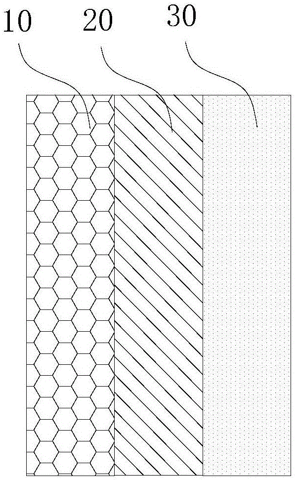
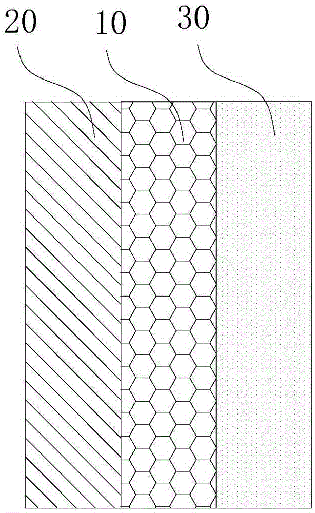
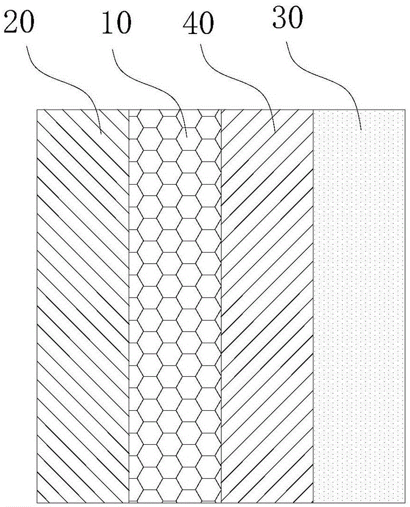
The invention provides an air cathode and a microbial fuel cell. The air cathode comprises a catalyst layer, a current collection layer and a diffusion layer, wherein the catalyst layer is made of nitrogen-doped carbon. Thus, through nitrogen-doped carbon, the embodiment of the air cathode is low in cost and efficient in catalysis and can play a better role in a neutral system of the microbial fuel cell.

Description

technical field [0001] The invention relates to the fields of environment, material and energy, and in particular, the invention relates to an air cathode and a microbial fuel cell for treating neutral media. Background technique [0002] Environmental issues and energy issues are two major problems facing the development of contemporary society. Purifying sewage while taking into account energy recovery is a new challenge for sewage treatment technology. Microbial fuel cell is an emerging sewage treatment technology, which can convert the chemical energy in the pollutants into electrical energy while treating sewage, and use the electricity-producing microorganisms attached to the anode to oxidize the organic matter in the sewage, while the cathode accepts electrons to complete the oxygen. reduction reaction. Among the cathodes of microbial fuel cells, air cathodes have attracted extensive attention because they can realize the direct diffusion and mass transfer of oxygen ...

Claims


Application Information

Patent Timeline
IPC IPC(8): H01M4/86H01M4/88H01M4/90H01M4/96H01M8/16
CPCH01M4/8605H01M4/8864H01M4/9075H01M4/96H01M8/16Y02E60/50
Inventor 张潇源黄霞蒂姆-帕特里克·费林格尔何伟华梁鹏张如范王秋莹布鲁斯·洛根
Owner TSINGHUA UNIV
Why Eureka
Try Eureka