A magnetic fluid coupling passive suspension axial flow pump

A coupled and passive technology, which is applied in the field of medical devices, can solve the problems that the incoming flow cannot be dispersed in time, the energy consumption of magnetic suspension bearings is high, and the suspension support force is limited, so as to reduce additional weight, improve reliability and impact resistance, The effect of low energy consumption

Active Publication Date: 2017-05-17
UNIV OF JINAN
View PDF7 Cites 1 Cited by
  • Summary
  • Abstract
  • Description
  • Claims
  • Application Information

AI Technical Summary

Problems solved by technology

[0007] 1. Actively controlled magnetic levitation mode is adopted, the control system is complicated, the volume is large, and the heat generation is large;
[0008] 2. Actively controlled magnetic suspension bearings have high energy consumption
[0013] However, the above three patents cannot meet these two requirements well at the same time, and the passive suspension support force is generated due to the gap between the rotor and the pump casing. The smaller the gap, the greater the force. The incoming flow has a certain speed. If the gap is too small, the incoming flow cannot be dispersed in time; if the gap is too large, the suspension support force will be limited, so how to solve the contradictory relationship between the two is also very important

Method used


Image

  • A magnetic fluid coupling passive suspension axial flow pump
  • A magnetic fluid coupling passive suspension axial flow pump
  • A magnetic fluid coupling passive suspension axial flow pump

Examples


Embodiment Construction

[0045] The present invention will be further described below in conjunction with the accompanying drawings and embodiments.

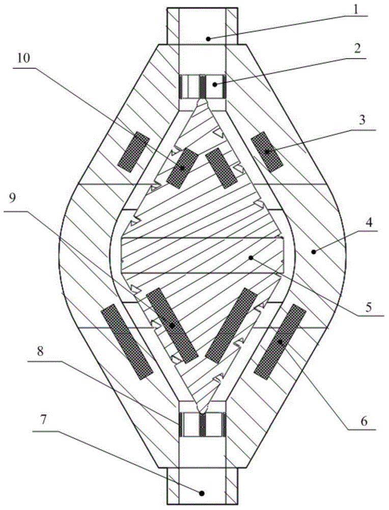
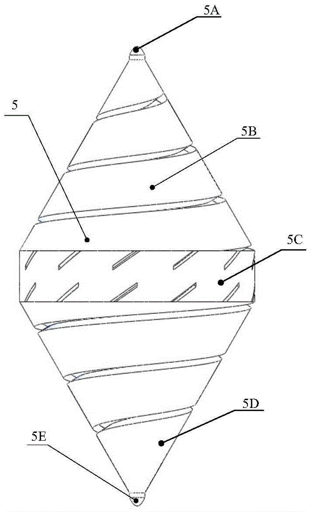
[0046] Such as figure 1 As shown, a magnetic-fluid coupled passive suspension axial flow pump includes a pump inlet 1, an inlet guide support ring 2, a suspended permanent magnetic ring 3, a pump casing 4, a rotor 5, an electromagnetic coil 6, and a pump outlet 7, Outlet diversion support ring 8, drive permanent magnet ring 9 and suspended permanent magnet magnet sheet 10. in,

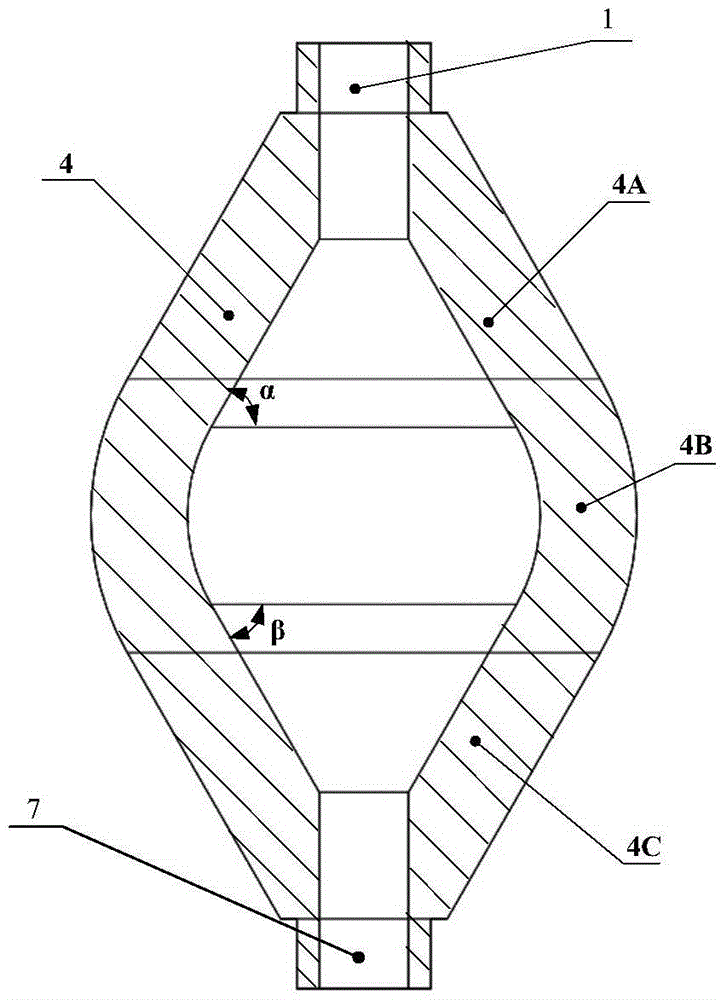
[0047] The shape of the inner cavity of the pump casing 4 is divided into three parts: the upper round table cavity 4A, the drum-shaped cavity 4B and the lower rounded table cavity 4C. The upper round table cavity 4A is embedded with a rectangular cross-sectional shape. The conical floating permanent magnet magnetic ring 3 (or permanent magnet magnetic sheet), the inverted round table cavity 4C housing of the bottom is embedded with an electromagnetic coil 6 that is a rectangu...


PUM


Abstract

The invention discloses a magnetic fluid coupling type passive suspension axial-flow blood pump which comprises a pump casing and a rotor, wherein the cavity in the pump casing gradually widens firstly and then gradually narrows in the direction from the pump inlet to the pump outlet; suspension permanent magnetic rings are arranged inside the upper half section of the pump casing; electromagnetic coils are arranged inside the lower half section of the pump casing; the rotor is arranged inside the cavity; suspension permanent magnetic rings are arranged inside the upper half section of the rotor, driving permanent magnetic rings are arranged inside the lower half section of the rotor, and a drainage groove is formed in the outer surface of the rotor; flow guiding supporting rings are arranged at the pump inlet and the pump outlet, and when the pump casing is filled with blood, the fixed flow guiding supporting rings support the rotating rotor. According to the invention, the magnetic fluid coupling type passive suspension bearing structure with the combined action of permanent magnetic suspension and hydraulic suspension is adopted, so that factors such as abrasion and frictional heating for inducing thrombus are avoided; the passive suspension manner is adopted, so that the energy consumption is less than that of an active control suspension bearing; therefore, the additional weight of the blood pump is effectively reduced, the development of the blood pump towards light-weight type and mini-type is facilitated.

Description

technical field [0001] The invention relates to medical equipment, in particular to a magnetic fluid coupling passive suspension axial flow blood pump. Background technique [0002] Artificial blood pumps have undergone three technological innovations from the pulsating blood pump that imitated the natural heart to the current rotary blood pump that can provide continuous flow. The technological innovations mainly revolve around the volume of artificial blood pumps, bearing heating and blood compatibility. Wait for the question to expand. [0003] The first generation of artificial blood pumps is mainly based on bionic design, using mechanical or electromagnetic drive to generate periodic volume changes to simulate the beating of the heart. Due to the general disadvantages of large volume, complex structure, and short lifespan in this generation of artificial blood pumps, most of them are only used as extracorporeal aids. The second-generation artificial blood pump general...

Claims


Application Information

Patent Timeline
Patent Type & Authority Patents(China)
IPC IPC(8): A61M1/10
CPCA61M60/419
Inventor 韩青赵诗奎孙选
Owner UNIV OF JINAN
Why Eureka
Try Eureka