Stone processing sewage treatment system

A sewage treatment system and stone processing technology, applied in the direction of filtration and separation, separation methods, chemical instruments and methods, etc., can solve the problems of high operation cost, large cost, water seepage, etc., and achieve low equipment operation cost and investment cost, The effect of simple equipment structure and efficient treatment process

Inactive Publication Date: 2015-12-23
丁西军
View PDF4 Cites 11 Cited by
  • Summary
  • Abstract
  • Description
  • Claims
  • Application Information

AI Technical Summary

Problems solved by technology

However, due to the large cost of the existing comprehensive treatment equipment for sawing sludge and high operating costs, some enterprises do not have such comprehensive sewage treatment equipment, but use various methods to settle the sawing sludge sewage, and the wastewater cannot be recycled. , sedimentation liquid and sedimentation powder are relatively polluting to the environment; even if some enterprises have installed a complete set of comprehensive sewage treatment equipment, they are basically not used due to the high operating costs, but are merely a formal operation to cope with the inspection of the superior
[0003] Existing stone sewage treatment equipment, such as filter press, ceramic filter, disc suction filter, although the filtering effect is good at the beginning, but after a long time of use (about one month), it will be close to being scrapped due to the oily substances in the wastewater But it cannot be used, and it cannot be applied to saw mud sewage containing oily substances for a long time
If chemicals are added to remove the oil in the sewage, not only the process control is unreliable, but also it is not conducive to the recycling of sewage by stone processing enterprises
In addition, during the filter press treatment, because the sewage contains a large amount of fine sand and sludge, there are gaps between the fine sand and sludge, the filter press effect is not ideal, and a large amount of water will still seep out after the press filter

Method used


Image

  • Stone processing sewage treatment system
  • Stone processing sewage treatment system
  • Stone processing sewage treatment system

Examples


Embodiment Construction

[0029] The present invention will be further described below with reference to the accompanying drawings and embodiments. In the following detailed description, certain exemplary embodiments of the present invention have been described by way of illustration only. Needless to say, as those skilled in the art would realize, the described embodiments may be modified in various different ways, all without departing from the spirit and scope of the present invention. Accordingly, the drawings and description are illustrative in nature and are not intended to limit the scope of protection of the claims.

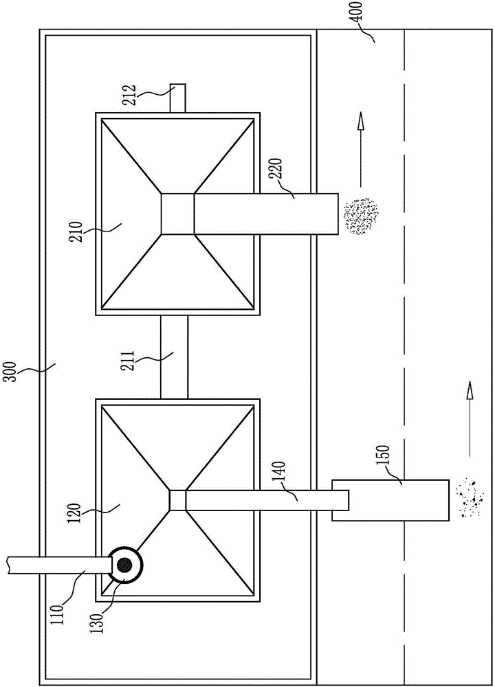
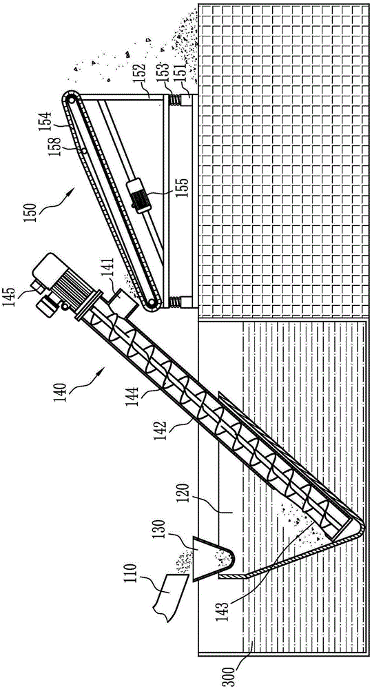
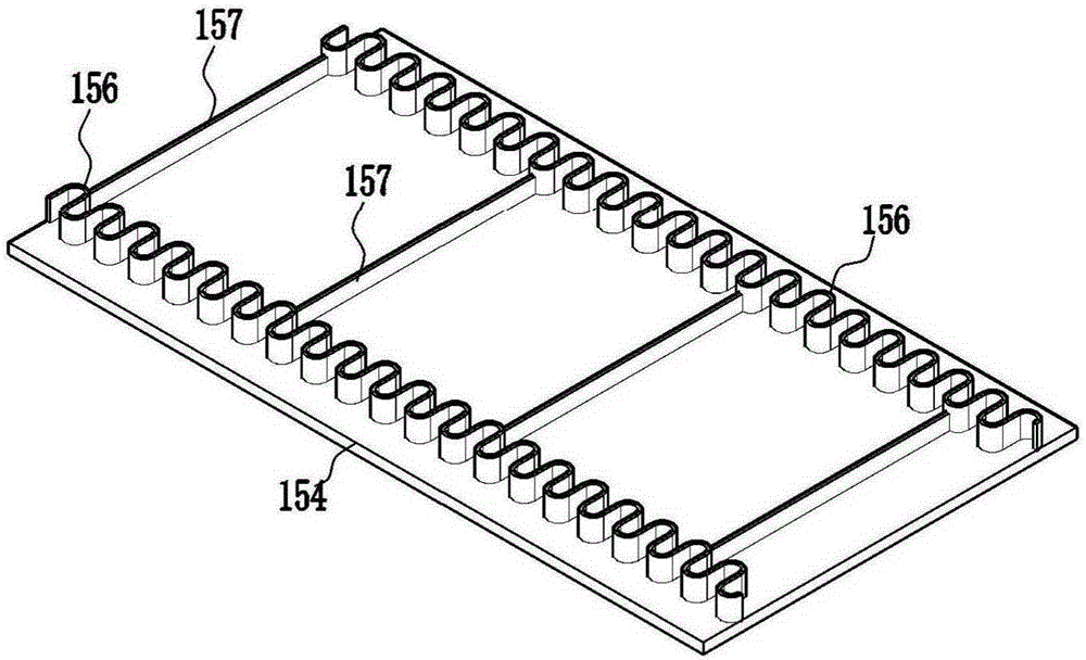
[0030] like Figure 1 to Figure 5 Shown, the stone processing sewage treatment system, including:

[0031] The sewage and sediment treatment device is arranged at the sewage outlet of the sewage pipe 110, and includes a sediment sedimentation tank 120 with a large upper end and a small lower end. The bottom of the sedimentation tank 120 is provided with a screw conveying device...


PUM


Abstract

The invention discloses a stone processing sewage treatment system which comprises a sewage sediment treating device and a sewage mud treating device. The sewage sediment treating device comprises a sediment settling pool with the upper end larger than the lower end, a filter funnel is arranged on a water inlet of the sediment settling pool, a spiral conveying device is arranged at the bottom of the sediment settling pool, and a sediment vibration dehydration conveying device is arranged on a sediment conveying outlet of the spiral conveying device. The sewage mud treating device comprises a mud settling pool with the upper end larger than the lower end, the mud settling pool is communicated with the sediment settling pool through a pipeline, and a mud settling dehydration conveying device is arranged at the bottom of the mud settling pool. The stone processing sewage treatment system is reasonable in structural design, equipment investment cost and running cost are low, sewage and sediment are separated fast and thoroughly, and the sewage treatment effect is good.

Description

technical field [0001] The invention relates to the technical field of sewage treatment equipment, in particular to a stone processing sewage treatment system. Background technique [0002] In recent years, the treatment of marble sawing mud sewage has always been the focus of environmental protection concerns of various manufacturers and governments, and a complete set of comprehensive sawing mud sewage treatment equipment has gradually appeared in the market. However, due to the high cost and high operating cost of the existing comprehensive sewage treatment equipment for sawing mud, some enterprises do not have such comprehensive sewage treatment equipment. , the sedimentation liquid and sedimentation powder have great environmental pollution; even if some enterprises have a complete set of comprehensive sewage treatment equipment, they are basically not used because of the high operating costs, but are only formal operations to cope with inspections by superiors. [000...

Claims


Application Information

Patent Timeline
Patent Type & Authority Applications(China)
IPC IPC(8): B01D36/04
Inventor 丁西军
Owner 丁西军
Why Eureka
Try Eureka