Coal grinding, impurity removing and coal feeding integrated device for power plant

A coal grinding and coal feeding technology, which is applied in the direction of solid separation, magnetic separation, conveyor control devices, etc., can solve the problems of affecting economic benefits, polluting the surrounding environment, and consuming too much power, so as to achieve reasonable connection structure design and improve economic benefits , the effect of reducing pollution emissions

Inactive Publication Date: 2015-12-23
中国大唐集团科学技术研究总院有限公司
View PDF5 Cites 12 Cited by
  • Summary
  • Abstract
  • Description
  • Claims
  • Application Information

AI Technical Summary

Problems solved by technology

[0002] With the development of large-capacity power generation units, the use of coal mills has increased, and the discharged pebble coal has become a heavy burden for thermal power plants. At present, the pebble coal discharged from coal mills is almost always discharged into the boiler slag discharge system or It is manually transported out of the boiler and discarded in the open air, wasting resources and polluting the surrounding environment. In addition, ordinary coal feeders cannot remove iron nails, iron wires, screws, etc. mixed in the coal, making these iron impurities easy to sinter in the boiler and difficult to clean. In addition, the usual coal feeder cannot keep track of the weight of the coal fed into the boiler at any time, it is not easy to control the ventilation rate, and the heat energy of the coal cannot be fully utilized, which affects economic benefits. The weight of the coal to be transported also uses multiple devices, which occupy a large area and consume a lot of power

Method used


Image

  • Coal grinding, impurity removing and coal feeding integrated device for power plant

Examples


Embodiment Construction

[0013] The following will clearly and completely describe the technical solutions in the embodiments of the present invention with reference to the accompanying drawings in the embodiments of the present invention. Obviously, the described embodiments are only some, not all, embodiments of the present invention. Based on the embodiments of the present invention, all other embodiments obtained by persons of ordinary skill in the art without making creative efforts belong to the protection scope of the present invention.

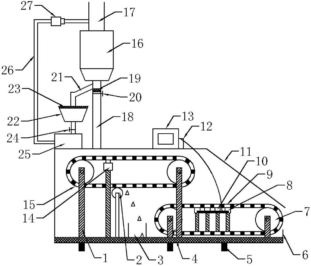
[0014] see figure 1 , in an embodiment of the present invention, an integrated equipment for coal grinding, impurity removal, and coal feeding for a power plant includes a casing 11, a coal-fired pipeline 18, and a pulverizer 25. The bottom of the casing 11 is provided with a seat leg 5, and inside the casing 11 The iron removal conveyor belt 15 is arranged on the upper left side of the weighing conveyor belt 9, and the iron removal conveyor belt 15 and the we...


PUM


Abstract

The invention discloses a coal grinding, impurity removing and coal feeding integrated device for a power plant. The coal grinding, impurity removing and coal feeding integrated device for the power plant comprises a shell, a fire coal pipeline and a pulverizer. Base legs are arranged at the bottom of the shell. An iron removing conveying belt is arranged in the shell and located above the left side of a weighing conveying belt. The iron removing conveying belt and the weighing conveying belt are both closed loops. A plurality of magnets are embedded in the iron removing conveying belt. A coal inlet is formed in the top of the shell and located in the upper portion of the left side of the iron removing conveying belt. A coal mill is arranged above the coal inlet. A raw coal pipeline is arranged at the upper end of the coal mill. By filtering, breaking and grinding pebble coal in raw coal in a circulating mode, the pebble coal can meet the combustion requirement of a combustion boiler and enter a coal feeder to be supplied to the boiler to be combusted; the design of a connecting structure is reasonable, and full combustion of the raw coal is guaranteed; in addition, when coal powder is thrown onto the iron removing conveying belt through the fire coal pipeline, scrap iron and screws in the coal powder can be attracted by the magnets on the iron removing conveying belt, thereby being prevented from falling onto the weighing conveying belt, and the quality of the coal powder is guaranteed.

Description

technical field [0001] The invention relates to the technical field of power plant equipment, in particular to an integrated equipment for coal grinding, impurity removal and coal feeding for a power plant. Background technique [0002] With the development of large-capacity power generation units, the use of coal mills has increased, and the discharged pebble coal has become a heavy burden for thermal power plants. At present, the pebble coal discharged from coal mills is almost always discharged into the boiler slag discharge system or It is manually transported out of the boiler and discarded in the open air, wasting resources and polluting the surrounding environment. In addition, ordinary coal feeders cannot remove iron nails, iron wires, screws, etc. mixed in the coal, making these iron impurities easy to sinter in the boiler and difficult to clean. In addition, the usual coal feeder cannot keep track of the weight of the coal fed into the boiler at any time, it is not...

Claims


Application Information

Patent Timeline
Patent Type & Authority Applications(China)
IPC IPC(8): B02C21/00B02C23/02B02C23/14B02C25/00B03C1/02B03C1/30B03C1/18B65G43/08
Inventor 孙佰仲
Owner 中国大唐集团科学技术研究总院有限公司
Why Eureka
Try Eureka