
Tooth crown blade locked through double screws in V-shaped positioning groove

A crown blade and positioning groove technology, which is applied in drilling/drilling equipment, drilling tool accessories, transportation and packaging, etc., can solve the problems of high production cost and complex structure, and achieve improved bearing capacity, large contact area, Good clamping reliability

Inactive Publication Date: 2015-12-23
SUZHOU AHNO PRECISION CUTTING TECH CO LTD
View PDF3 Cites 1 Cited by
  • Summary
  • Abstract
  • Description
  • Claims
  • Application Information

AI Technical Summary

Problems solved by technology

These positioning and locking methods have their own characteristics, but most of them have complex structures and high production costs.

Method used


Image

  • Tooth crown blade locked through double screws in V-shaped positioning groove
  • Tooth crown blade locked through double screws in V-shaped positioning groove
  • Tooth crown blade locked through double screws in V-shaped positioning groove

Examples


Embodiment Construction

[0021] Below in conjunction with accompanying drawing, technical solution of the present invention will be further described:

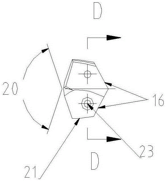
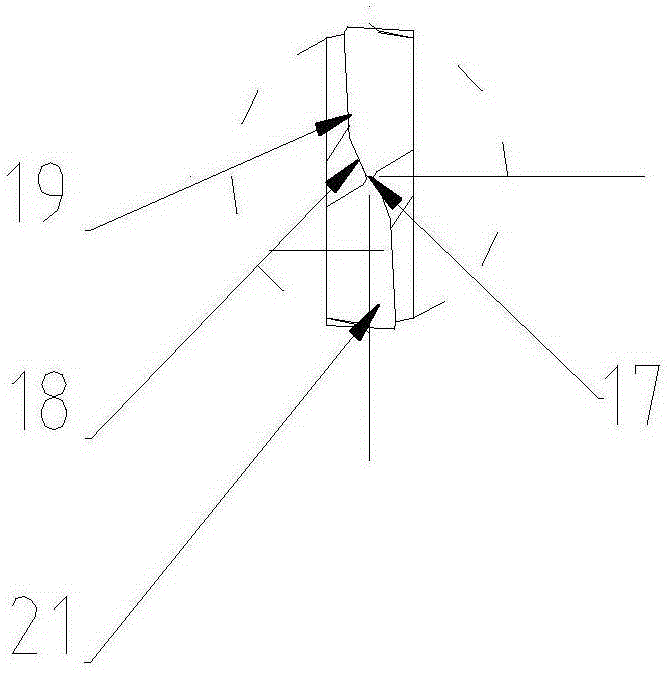
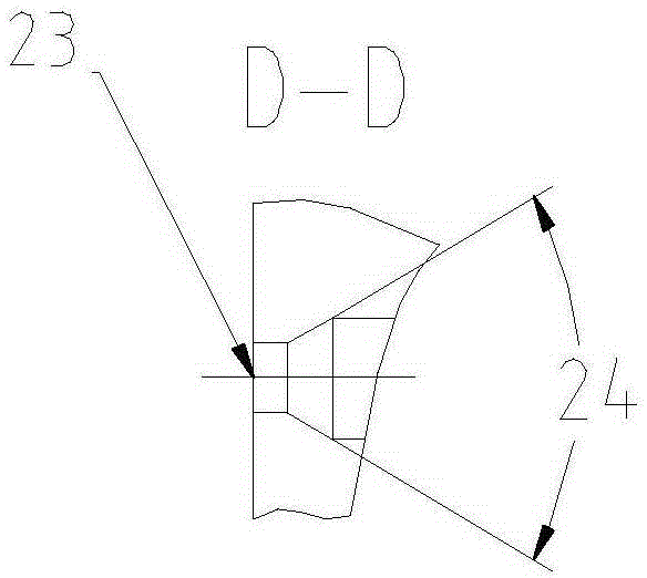
[0022] Such as Figure 1~4 As shown, the crown blade is locked by double screws in the V-shaped positioning groove, and the right end of the crown blade is provided with a V-shaped positioning surface 16 for matching with the positioning surface of the working part of the drill pipe. The included angle of the V-shaped positioning surface 16 is 90° ~140°, the left end of the crown insert is provided with a cutting edge consisting of a chisel edge 17, a transition edge 18 and a main cutting edge 19, the intersection line of the chip flute and the flank forms the main cutting edge 19, and the main cutting edge The formed included angle is apex angle 20°, the angle is 120-140°, the intersection line of the two flanks forms a chisel edge 17, and a transition edge 18 is ground between the main cutting edge and the chisel edge; The tooth crown edge 21, the ...


PUM


Abstract

The invention relates to a tooth crown blade locked through double screws in a V-shaped positioning groove. A V-shaped positioning face matched with a positioning face of a working portion of a drilling rod is arranged at the right end of the tooth crown blade, and a cutting edge composed of a transverse edge, a transition edge and a main cutting edge is arranged at the left end of the tooth crown blade; the main cutting edge is formed by the crossing lines of a chip removal groove and rear cutter faces, and the transverse edge is formed on the crossing lines of the two rear cutter faces; and the transition edge is arranged between the main cutting edge and the transverse edge in a polishing manner. A tooth crown edge side is arranged on the tooth crown blade in the diameter direction and is spirally provided with a wide cylindrical face, and the tooth crown blade is provided with a ladder hole where a compressing screw is mounted; and the axis of the ladder hole is perpendicular to the mounting face of the blade, and the position of the ladder hole is opposite to the position of a fastening screw hole in a drilling rod; and the blade locked through the double screws in the V-shaped positioning groove is large in contact area, high in bearing force, good in clamping reliability and suitable for large feeding cutting.

Description

technical field [0001] The invention relates to a double-screw locking crown blade in a V-shaped positioning groove. Background technique [0002] The crown drill bit is a combined drill bit in which the head is made of cemented carbide or other high-performance materials, and the drill rod is made of alloy steel. It has the advantages of low cost of use and large processing range. [0003] At present, there are many combinations of the head and the drill pipe of the crown drill bit. For example, there are "column pin positioning, screw through locking", "broken line groove positioning, positive and negative buckle screw locking", "cross V-shaped surface positioning, rear pull screw locking", "open pin positioning, non-screw rotation Clamping" and many other forms. These positioning and locking methods have their own characteristics, but most of them have complex structures and high production costs. Contents of the invention [0004] The purpose of the present inventi...

Claims


Application Information

Patent Timeline
Patent Type & Authority Applications(China)
IPC IPC(8): B23B51/00
CPCB23B51/00B23B2251/04B23B2251/08B23B2251/14
Inventor 刘伟蒋长青叶鑫王晓琴
Owner SUZHOU AHNO PRECISION CUTTING TECH CO LTD
Learn More