
Slider Superfinishing Machine

A technology of ultra-finishing machines and sliders, which is applied in the direction of grinding racks, grinding slides, grinding machines, etc. It can solve the problem that the arc profile and surface roughness of the raceway are not easy to be guaranteed, and the profile of the grinding wheel is easy to deform, etc. problem, achieve better anti-seismic effect, lower manufacturing difficulty, and improve processing efficiency

Active Publication Date: 2017-05-10
LISHUI UNIV
View PDF6 Cites 0 Cited by
  • Summary
  • Abstract
  • Description
  • Claims
  • Application Information

AI Technical Summary

Problems solved by technology

Due to the small diameter of the grinding wheel, the molding line of the grinding wheel is easily deformed due to threshing and wear of the grinding wheel during the grinding process.
Therefore, the arc profile and surface roughness of the raceway are not easy to guarantee

Method used


Image

  • Slider Superfinishing Machine
  • Slider Superfinishing Machine
  • Slider Superfinishing Machine

Examples


Embodiment Construction

[0030] The present invention will be further described below in conjunction with accompanying drawing:

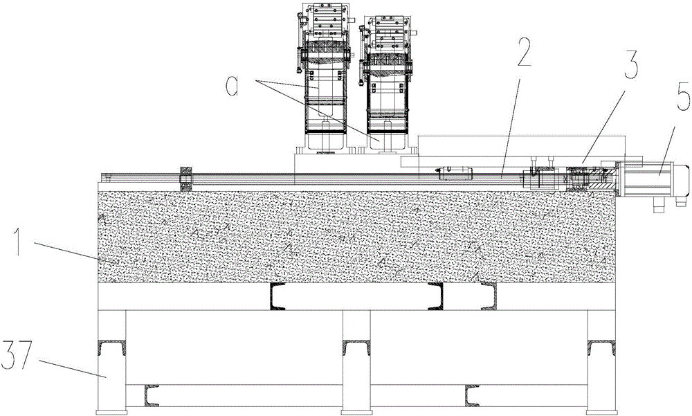
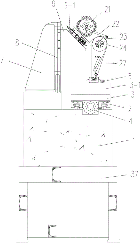
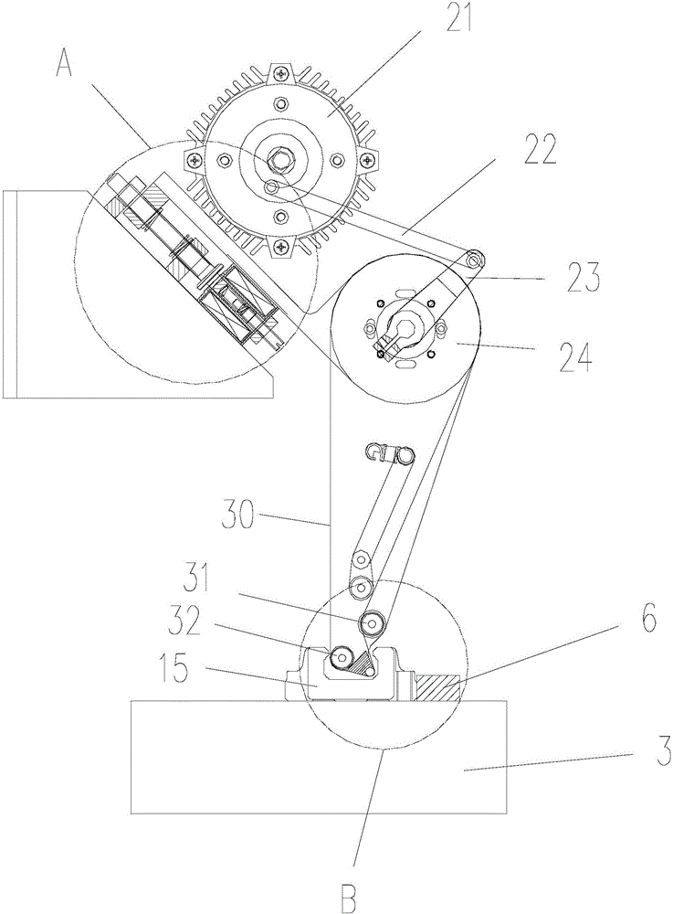
[0031]Referring to the accompanying drawings: the slider ultra-finishing machine in this embodiment includes a bed 1, the bed 1 is fixed on the frame 37, a transverse guide rail 2 is installed on the front of the bed 1, and a workbench 3 is installed on the transverse guide rail 2 The bed 1 is equipped with a screw 4 that drives the workbench 3 to slide and a servo motor 5 that drives the screw to rotate. The workbench 3 is equipped with an electro-permanent magnetic chuck 3-1, and the electro-permanent magnetic chuck 3-1 is equipped with a positioning plate 6. The rear part of the bed 1 is equipped with a superfinishing mechanism a for processing the inner raceway of the slider. The superfinishing mechanism a includes a fixing seat 7, and a longitudinal guide rail 8 is installed on the front end of the fixing seat 7. The longitudinal guide rail 8 The lifting seat 9 is inst...


PUM


Abstract

A sliding block superfinishing machine comprises a machine body, wherein horizontal guide rails are installed on the front portion of the machine body, a working table is installed on the horizontal guide rails, a lead screw driving the working table to slide and a servo motor driving the lead screw to rotate are installed on the machine body, and a permanent magnetic chuck and a positioning plate are installed on the working table; a superfinishing mechanism used for machining an inner roller path of a sliding block is installed on the rear portion of the machine body, a swing motor is installed on an oblique sliding base, a connecting rod is connected to an output shaft of the swing motor, and a swing arm is connected to the outer end of the connecting rod; a driving shaft is installed at the lower end of the oblique sliding base, bearings are installed at the two ends of the driving shaft and located on the oblique sliding base through fastening sleeves, and one end of the driving shaft is connected with the swing arm; connecting plates are connected to the left side and right side of the oblique sliding base respectively in a rotary mode, and positioning holes and positioning screws are arranged between the connecting plates and the fastening sleeves and the oblique sliding base; an arc-shaped groove is formed in one side of the outer end of each connecting plate, a driven shaft is installed in each arc-shaped groove, and a grinding belt is arranged between the driving shaft and each driven shaft in a sleeving mode.

Description

technical field [0001] The invention relates to a slider superfinishing machine. Background technique [0002] At present, the processing of the guide rail slider is firstly cut, and after cutting and forming, it is heat treated and then ground. Due to the limitation of the structure of the slider raceway, the diameter of the grinding wheel used for grinding the raceway is relatively small, usually the width of the track is generally taken. Such as: 15 guide rail, grinding wheel diameter is Φ15~Φ10. 20 guide rail grinding wheel diameter is Φ20~Φ15. 25 guide rail, grinding wheel diameter is Φ25~Φ20; grinding wheel correction generally adopts diamond roller forming correction. Due to the small diameter of the grinding wheel, it is required to meet the requirements of the grinding line speed, and the grinding wheel rotates at a high speed. Due to the small diameter of the grinding wheel, during the grinding process of the formed grinding wheel, the profile of the grinding whe...

Claims


Application Information

Patent Timeline
Patent Type & Authority Patents(China)
IPC IPC(8): B24B21/00B24B21/18B24B21/20B24B55/00B24B41/02
CPCB24B21/006B24B21/18B24B21/20B24B41/02B24B55/00
Inventor 吕永昌叶泳东吕鑫楠
Owner LISHUI UNIV
Learn More