
Chemical grouting sealing device and method for underground formation sealing

An isolation device and grouting technology, which is applied in the directions of sealing/isolation, earthwork drilling, wellbore/well parts, etc., can solve the problem that the pressure bearing capacity cannot reach the ideal state, the material strength of the expansion cylinder is low, and the expansion agent is easily damaged. Decomposition and other problems, to achieve the effect of flexible site adaptability, good sealing adaptability, and large volume expansion rate

Active Publication Date: 2017-11-24
INST OF ROCK & SOIL MECHANICS CHINESE ACAD OF SCI
View PDF5 Cites 2 Cited by
  • Summary
  • Abstract
  • Description
  • Claims
  • Application Information

AI Technical Summary

Problems solved by technology

[0007] The problems of mechanical and hydraulic packers are: 1) The structure is complex and the sealing effect is poor; 2) The damage to the casing is serious, and it is difficult to achieve multiple layers; 3) It cannot be self-compensated and adjusted, and it must be connected with a thermal expansion tube;
The problems are: 1) The expansion agent is easy to decompose, has poor stability, and is difficult to unsealing; 2) The material strength of the expansion cylinder is low, and the pressure resistance is poor; 3) The overall deformation increases the difficulty of the packer going downhole, which affects the sealing and compression resistance; 4) Due to the Corrosion or damage to the pipe caused the lax sealing of the seal, resulting in the failure of the entire operation; 5) The self-expanding material may not be soaked in a suitable medium when it is lowered into the wellbore and cannot expand rapidly; 6) The expansion medium is blocked and the material is completely damaged. Long expansion time leads to delay in well completion cycle and unsatisfactory pressure bearing capacity
[0010] There are many problems in the existing packer technology as mentioned above, and it still cannot meet the needs of certain occasions.
For example, in shallow formations less than 200m, the pore water pressure, temperature, fluid medium and other conditions are good, and expensive and complicated hydraulic or mechanical packers are not required, and the technical indicators of self-expandable packers (if encountered The volume expansion rate of the water-expandable rubber cartridge is generally 4 times) and the actual sealing effect may not meet the requirements

Method used


Image

  • Chemical grouting sealing device and method for underground formation sealing
  • Chemical grouting sealing device and method for underground formation sealing
  • Chemical grouting sealing device and method for underground formation sealing

Examples


Embodiment 1

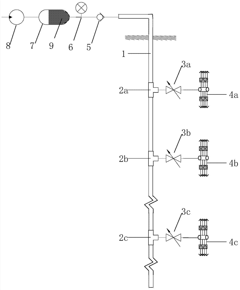
[0072] Such as figure 1 As shown, the chemical grouting isolation device suitable for downhole formation sealing of vertical wells includes a grouting pipe 1; a first tee 2a; a second tee 2b; a third tee 2c; Pressure control valve 3a; second self-operated sectional pressure control valve 3b; third self-operated sectional pressure control valve 3c; first spray plug 4a; second spray plug 4b; third spray plug 4c ; Throttle valve 5; Pressure gauge 6; Relay container 7; Manual pump 8; Chemical slurry 9.

[0073] The input end of the intermediate container 7 is provided with a manual pump 8, the output end of the intermediate container 7 is connected with the grouting pipe 1 through the throttle valve 5, and the output end of the intermediate container 7 is also provided with an output for detecting the intermediate container 7. The pressure gauge 6 of the terminal pressure, the grouting pipe 1 is vertically arranged underground, and the grouting plugs are installed at the position...

Embodiment 2

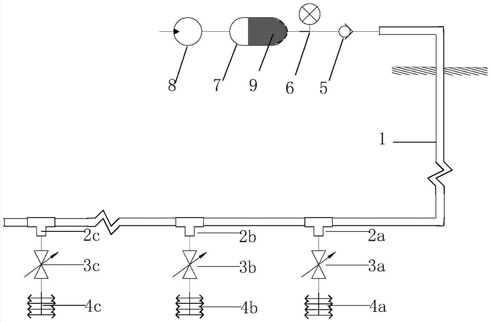
[0088] Such as figure 2 As shown, the chemical grouting isolation device suitable for downhole formation sealing of horizontal wells, including grouting pipe 1; first three-way 2a; second three-way 2b; third three-way 2c; Pressure control valve 3a; second self-operated sectional pressure control valve 3b; third self-operated sectional pressure control valve 3c; first spray plug 4a; second spray plug 4b; third spray plug 4c ; Throttle valve 5; Pressure gauge 6; Relay container 7; Manual pump 8; Chemical slurry 9.

[0089] The input end of the intermediate container 7 is provided with a manual pump 8, the output end of the intermediate container 7 is connected with the grouting pipe 1 through the throttle valve 5, and the output end of the intermediate container 7 is also provided with an output for detecting the intermediate container 7. The pressure gauge 6 of the end pressure, the grouting section of the grouting pipe 1 is set horizontally underground, and the grouting plug...

Embodiment 3

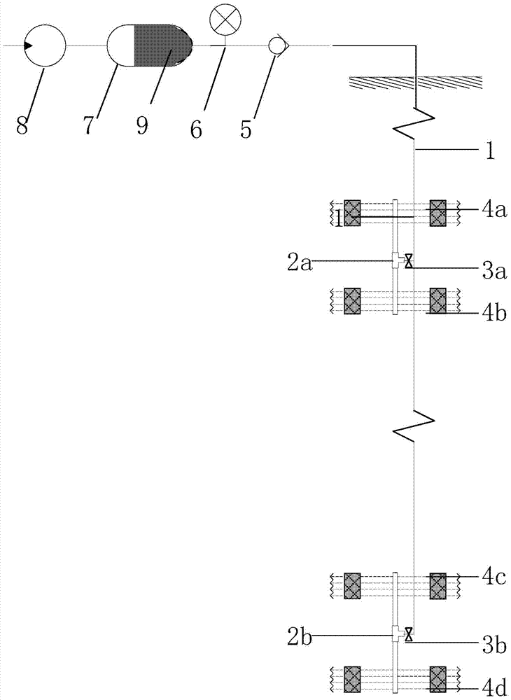
[0094] Such as image 3 As shown, the chemical grouting isolation device suitable for downhole formation sealing of vertical wells includes a grouting pipe 1; a first tee 2a; a second tee 2b; a third tee 2c; Pressure control valve 3a; second self-operated sectional pressure control valve 3b; third self-operated sectional pressure control valve 3c; first spray plug 4a; second spray plug 4b; third spray plug 4c ; Throttle valve 5; Pressure gauge 6; Relay container 7; Manual pump 8; Chemical slurry 9.

[0095] The input end of the intermediate container 7 is provided with a manual pump 8, the output end of the intermediate container 7 is connected with the grouting pipe 1 through the throttle valve 5, and the output end of the intermediate container 7 is also provided with an output for detecting the intermediate container 7. The pressure gauge 6 of the terminal pressure, the grouting pipe 1 is vertically arranged underground, and the grouting plugs are installed at the position...


PUM


Abstract

The invention discloses a chemical grouting isolation device for downhole formation sealing, which comprises a relay container, the input end of the relay container is provided with a manual pump, and the output end of the relay container is connected with a grouting pipe through a throttle valve , the output end of the relay container is also equipped with a pressure gauge for detecting the pressure of the output end of the relay container, and a spray plug is set at the set position underground, and the spray plug at each set position is controlled by self-operated segmental pressure The valve communicates with the grouting section where the grouting pipe is located underground. Also disclosed is a chemical grouting sealing method for underground formation sealing. The invention has no damage to the casing, and easily realizes multi-layer isolation; the volume expansion rate is larger, and the downhole sealing adaptability is better, and the grouting operation at different depths can be realized through different injection pressure values ​​of a grouting pipe at the wellhead.

Description

technical field [0001] The invention relates to the field of stratum isolation, in particular to a chemical grouting isolation device for downhole formation sealing, and also to a chemical grouting isolation method for downhole formation sealing, which is suitable for shallow formation sealing, especially for underground fluid separation. The upper and lower strata are separated by layer sampling. Background technique [0002] A packer is a downhole tool that uses sealing elements to close the annular space between the pipe string and the wellbore. Its function is to separate the whole well by layers, or effectively seal off the high water-bearing layer, so as to produce in different layers or implement necessary technical measures. Widely used in drilling, well completion, reservoir stimulation, water control and water plugging, fracturing, acidification, and chemical injection in the process of oil and gas wells, high acid gas, coalbed methane, etc. Separated from upper / ...

Claims


Application Information

Patent Timeline
Patent Type & Authority Patents(China)
IPC IPC(8): E21B33/13
Inventor 刘学浩李琦肖威李小春宋然然方志明
Owner INST OF ROCK & SOIL MECHANICS CHINESE ACAD OF SCI
Learn More