Flushing system and method for lubricating oil system of steam turbine generator unit

A technology for a steam turbine generator set and a flushing system, which is applied in the direction of cleaning methods using liquids, engine components, machines/engines, etc. The effect of shortening the installation period, avoiding secondary pollution and improving flushing efficiency

Active Publication Date: 2015-12-23
POWERCHINA SEPCO1 ELECTRIC POWER CONSTR CO LTD
View PDF5 Cites 1 Cited by
  • Summary
  • Abstract
  • Description
  • Claims
  • Application Information

AI Technical Summary

Problems solved by technology

[0004] Using the above method to improve the cleanliness of oil quality, the cycle is relatively long, and there are many factors affecting oil quality
After the first step of flushing is completed, it is necessary to cut off a large number of temporary pipes and restore the formal pipes, which causes secondary pollution of oil quality. During the implementation process, electric fire welding is required, which has great potential safety hazards
And in the next second step, it is necessary to repeat all the work within the scope of step one, wasting a lot of time
The lubricating oil storage and delivery system uses carbon steel pipes, which are prone to rust after long-term use and pollute the oil quality
[0005] At present, the pipelines of the lubricating oil storage and delivery system of the unit are designed as carbon steel pipelines, which requires that the pipelines must be pickled before installation, so the quality of pickling also directly affects the cleanliness of the lubricating oil, but the carbon steel pipelines are affected by pickling. Due to the influence of the type and concentration of the acid, the skill level of the pickling personnel, etc., the quality of the pickling is also uneven, which leads to the frequent occurrence of rusting after the pipeline is installed, resulting in oil pollution

Method used


Image

  • Flushing system and method for lubricating oil system of steam turbine generator unit

Examples


Embodiment Construction

[0030] The present invention will be further described below in conjunction with the accompanying drawings and embodiments.

[0031] The flushing method of the lubricating oil system of the turbogenerator set includes:

[0032] Step 1. Connect the oil inlet and return pipes of the bearing seat to the bearing seat according to the designed working state; in this way, there is no need to connect temporary pipes outside the bearing seat;

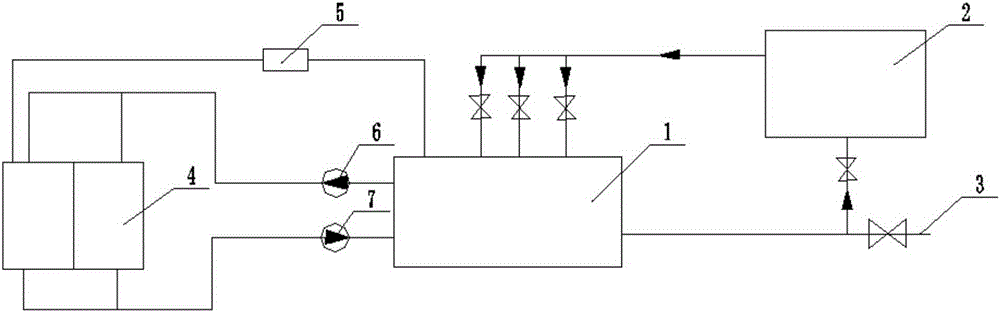
[0033] The main oil tank 1 is connected to the oil inlet of the first oil filter unit 2 through the oil pipeline, and the first oil filter unit 2 adopts a large-flow oil filter unit (such as a DHCX-600 type steam turbine oil system large-flow flushing oil filter unit), and a large-flow filter unit The output port of the oil machine is connected in parallel with three branches, one branch is a self-circulation pipeline, which is directly connected to the inside of the main oil tank 1, as a self-circulation flushing source of the oil tank, there ...


PUM


Abstract

The invention discloses a flushing system and method for a lubricating oil system of a steam turbine generator unit. The method includes the first step of connecting a bearing pedestal with an oil inlet and return pipe according to the design state, the second step of removing a bearing oil inlet pipe inside the bearing pedestal, the third step of starting a first oil filtering machine and cleaning a main oil tank and the bearing pedestal, the fourth step of shutting down the first oil filtering machine, pouring all lubricating oil of the main oil tank into an oil storage tank through a second oil filtering machine, and cleaning the main oil tank and the bearing pedestal, and the fifth step of pouring the lubricating oil in the oil storage tank into the main oil tank through the second oil filtering machine, starting the first oil filtering machine, sampling the lubricating oil of the main oil tank for testing, recovering an oil pipe inside the bearing pedestal and finishing the flush if the oil meets NAS7, and carrying out the steps 3-5 repeatedly if the oil does not meet NAS7. The lubricating oil can return to the main oil tank after directly entering the bearing pedestal and being flushed, so that provisional measures taken for oil inlet and return pipes of bearing pedestals are reduced, the cost is reduced, the installation period is shortened, and oil is prevented from secondary pollution.

Description

technical field [0001] The invention relates to the technical field of lubricating oil cleanliness, in particular to a flushing system and a flushing method for a lubricating oil system of a steam turbine generator set. Background technique [0002] The lubricating oil system of a turbogenerator set is a rather complicated system including a large number of large and small diameter pipes and lubricating oil. Even small harmful particles may cause damage to the unit bearings, resulting in costly downtime. [0003] At present, the capacity of newly installed units at home and abroad is increasing day by day, and its lubricating oil system is correspondingly more complicated, and the oil filling volume of the system is also gradually increasing. At the present stage, 300MW and above units generally use large-flow oil filter as the flushing power when purifying the oil quality of the turbo-generator set. Outlet: 1. Connect to the inlet pipeline of the main oil pump of the front...

Claims


Application Information

Patent Timeline
Patent Type & Authority Applications(China)
IPC IPC(8): F01D25/20B08B3/02B08B13/00
Inventor 缑海琛王彦成刘慧兰
Owner POWERCHINA SEPCO1 ELECTRIC POWER CONSTR CO LTD
Why Eureka
Try Eureka